COMPAX-M /-S (L) COMPAX User Guide Compact Servo Controller From software version V6.26 C ER TIFIE D DIN EN ISO 9001 U A M Q We automate motion LI TY SYS TE Reg. Nr. 36 38 Subject to technical modification. Data correspond to the state of technical development at the time of printing. Parker Hannifin GmbH EMD Hauser P. O. Box: 77607-1720 Robert-Bosch-Str. 22 D-77656 Offenburg, Germany Phone: +49 (0)781 509-0 Fax: +49 (0)781 509-176 http://www.parker-emd.com 11.10.
COMPAX-M / -S Contents 1. Contents 1. Contents ...................................................................................................2 2. Unit assignment: ....................................................................................7 3. Safety instructions .................................................................................8 3.1 General dangers ........................................................................................8 3.2 Safe working practices ..........
7.4.4 7.5 COMPAX 25XXS unit characteristics ....................................................30 7.5.1 7.5.2 7.5.3 7.5.4 7.6 Connector and terminal assignment for COMPAX 1000SL ........................... 40 Connector assignment COMPAX 1000SL (overview) .................................... 42 Mounting and dimensions COMPAX 1000SL ................................................. 43 Safety chain / emergency stop functions .......................................................
Contents 8.2.3 8.2.4 8.2.5 8.2.6 8.2.7 8.2.8 8.3 Installing ServoManager................................................................................... 91 Configuring COMPAX ....................................................................................... 91 Individual configuration of synchronous motors........................................... 91 Positioning and control functions .........................................................95 8.4.1 8.4.2 8.4.3 8.4.4 8.4.5 8.4.6 8.4.7 8.4.8 8.4.
8.5 Optimization functions .........................................................................125 8.5.1 8.5.2 8.5.3 8.5.4 8.6 Optimization parameters ................................................................................ 127 Speed monitor ................................................................................................. 132 Optimization display .......................................................................................
COMPAX-M / -S Contents 9.7.1 9.7.2 9.7.3 9.7.4 9.7.5 9.7.6 9.7.7 9.8 External control panel (not available for COMPAX 1000SL) ....................... 187 Terminal module for COMPAX 1000SL (EAM) .............................................. 188 EAM5/01: DC feed for COMPAX-M................................................................. 189 EMC measures ................................................................................................ 191 9.7.4.1 Power filter .............................
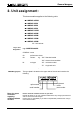
General dangers 2. Unit assignment: This documentation applies to the following units: ! COMPAX 10XXSL ! COMPAX 25XXS ! COMPAX 45XXS ! COMPAX 85XXS ! COMPAX P1XXM ! COMPAX 02XXM ! COMPAX 05XXM ! COMPAX 15XXM ! COMPAX 35XXM XX: Unit variants Key to unit designation e.g.: COMPAX 0260M: COMPAX: name 02: performance class 60: Variant e.g. "00": Standard model "60": electronic transmission M: unit type "M": multi-axis model "S": single-axis unit ...
Safety instructions COMPAX-M / -S 3. Safety instructions 3.1 General dangers General dangers when safety instructions are not complied with The unit described contains leading edge technology and is operationally reliable. However, hazards may occur if the unit is employed incorrectly or for improper use. Energized, moving or rotating parts can ! cause fatal injury to the user ! cause material damage Proper use This unit is designed for use in high voltage units (VDE0160).
Conditions of warranty 3.4 Conditions of warranty The unit must not be opened. Do not make any alterations to the unit, except for those described in the User Guide. ! Only activate inputs, outputs and interfaces as described in the User Guide. ! When installing units, ensure that the heat sinks receive sufficient ventilation. ! Secure units as per the assembly instructions contained in the start-up manual using the securing bores provided for this purpose.
COMPAX-M / -S Switch-on status 5. Switch-on status 5.1 Configuration when supplied When supplied, COMPAX is not configured. Parameter P149 is set to "0": P149="0": COMPAX is not configured and switches to OFF mode when switched on (24V DC and operating voltage) (motor switched off). In addition to this, when switched on, all parameters (apart from bus settings P194, P195, P196 and P250) are set to their default values.
Commissioning After 24V DC of control voltage is switched on, COMPAX has two statuses available once the initialization phase has been completed: 1. COMPAX is OFF COMPAX is not configured (P149="0") or with COMPAX XX70: I12="0" (final stage blocked). Now configure COMPAX (e.g. using the ServoManager / ParameterEditor). Set P149="1" Configuration is accepted with VC and VP of COMPAX. 2. COMPAX displays error E57 COMPAX is configured (P149="1"). However, operating voltage is not present.
Switch-on status 5.3 COMPAX-M / -S Equipment replacement Previous software ≥V2.0 Procedure for copying the complete COMPAX setting onto a new unit Start ServoManager. ! Connect old COMPAX via RS232. ! Use menu "Insert: Axis: From controller" to set up an axis which contains all COMPAX settings (all parameters: including system parameters, data records and (with COMPAX XX70) existing curves). ! Connect new COMPAX.
Equipment replacement 6. Conditions for usage - for CE-compliant operation in industrial and business sectors The EU guidelines on electromagnetic compatibility 89/336/EEC and electrical means of production for use within particular voltage limits 73/23/EEC are satisfied, if the following peripheral conditions are complied with. Only operate the units in the condition in which they are supplied, i.e. with all housing plates and the front cover.
COMPAX-M / -S Start-up manual 7. Start-up manual Compact Servo Controller 7.1 Overview: 7.1.1 Components required In addition to a COMPAX, you will require the following components for a COMPAX application: ! a motor with or without a transmission. ! mains supply. ! emergency stop circuit. ! various cables for connecting components. ! motor cable and resolver cable. ! supply line for voltage supply. ! supply line for 24V DC control voltage.
Connector assignment / cable Overview of unit technology 7.1.2 Overview of unit technology COMPAX-M and COMPAX-S ! housing and assembly technology and ! power areas.
COMPAX-M / -S Start-up manual COMPAX 1000SL Supply Up to max. 1*250V AC (integrated power unit) Dimensions (DxHxW): 146*180*85 [mm] In 24 V DC X14 HEDA Input + - X6 X15 H2 Power 1 kVA Out X4 HEDA PE R Dum p X12 - Brake W PE + V U X19 PE N L1 230 V AC X2 Input / Output COMPAX - SL COMPAX 25XXS Motor Resolver Encoder X1 X13 Fieldbus In Fieldbus Out X5 X7 RS232 Limit Switch X3 X17 H1 Design: Supply Up to max.
7.2 Connector assignment / cable Connector and terminal assignment Unit hardware COMPAX-M unit features COMPAX-M unit features Technical data 7.2.
COMPAX-M / -S Start-up manual 7.2.2 COMPAX-M system network, NMD10 / NMD20 mains module A COMPAX-M drive system consists of one mains module and one or more drive controllers. The units are coupled with one another with flatband cables (see below). These are arranged behind the front plate cover of the power unit and the drive controller. The power unit converts mains power (up to 3 * 500V AC) into DC current for the intermediate circuit.
Unit side U V W PE brake SUPPL Y CO D IG T A I L Mo ti o n &o Cn tr o l Nu mb e r S ta tu s Vu l e a - Re a d y X7 En te r - E ro r X8 X8 X1 0 En te r - E ro r + black 5 free black 4 En te r Re a d y X8 O tu u p t X8 T se t Co n tr o l X1 X1 O tu u p t T se t Co n tr o l PE+ - X1 0 In p u t O tu u p t T se t + - RS 2 3 2 X1 0 U V W PE brake L1 L2L3 PE 24V E ro r X6 In p u t X9 5 Nu mb e r RS 2 3 2 In p u t Co n tr o l S ta tu s X6 RS 2 3 2 OT U 4 Vu
COMPAX-M / -S Start-up manual 7.2.3 COMPAX-M dimensions/installation The specific design of the COMPAX-M controller allows for wall installation (distance: 61mm in COMPAX P1XXM and 86mm in larger units) in two different ways. Direct wall installation and dimensions of COMPAX-M and the mains modules.
Connector assignment / cable Connector assignment COMPAX-M X10/9 X10/10 X10/11 X10/12 X10/13 X10/14 X10/15 X10/16 X9/1 X9/2 X9/3 X9/4 X9/5 X9/6 X9/7 Technical data X6/9 X6/7 X6/6 X6/5 X6/4 X6/3 X6/8 CTS RTS DSR GND DTR TxD X6/2 RxD X3/2 0V Configuration Positioning and control functions X3/1 +24 V -LS PE +5V X18/+ X18/- DA-channel 0 X17/1 DA-channel 1 X17/2 (option D1) O5 O7 O8 I10 Sig.MN X17/7 Sig. E2 X17/8 I11 Sig.
COMPAX-M / -S Start-up manual 7.3 Mains module NMD10/NMD20 The mains module ensures the supply of current to the COMPAX-M (not COMPAX 35XXM) axis controller and the SV drive connected into the network. It is connected to the 3-phase power supply with 3 * 400V AC and PE. 24V DC voltage must be provided for the control electronics. 7.3.
Connector assignment / cable NMD connector assignment 7.3.3 NMD connector assignment X1/3 X1/4 X1/5 X1/6 +24V L1 L2 L3 PE GND X1: voltage supply X8 P stand by S +24V +24V 15V-24 V emerg.
COMPAX-M / -S Start-up manual Overvoltage limitation Energy recuperated during braking is stored in the supply capacitors. The capacity and storable energy is: NMD10/NMD20: 1100µ µF / 173 Ws If the energy recuperated from braking causes overvoltage, then ballast resistances are engaged. Activation of the internal ballast resistance for NMD20 The internal ballast resistance is activated by a bridge between +LS and X5/1. In the NMD20 delivery status this bridge is fitted.
Connector assignment / cable Technical data / power features NMD If a phase malfunctions, no displays appear LED red Error LED green Ready Possible errors off on on off no errors Heat sink temperature too high or ! error in logic voltage (24V DC too low or unit is defective) Technical data ! Emergency stop is activated and ready contact is released. Ballast switch overloaded or ! undervoltage (<100V DC or <80V AC). ! Configuration on Ready contact and green LED are coupled.
COMPAX-M / -S Start-up manual 7.4 COMPAX 35XXS unit features The 35 kW servo control COMPAX 35XXM - a performance upgrade to the COMPAX family. ! Compact unit with output currents of 50 Aeff / 100 Aeff (<5s) with integrated power unit. ! Additional COMPAX-M controllers of up to 15 KW can be arranged in rows. 7.4.
Connector assignment / cable Installation and dimensions of COMPAX 35XXM Plan view external ballast resistor AC - voltage up to 500V AC motor brake 24V control voltage F1 3.16A motor Unit hardware COMPAX 35XXS unit features - + L2 L3 Mains Input PE X 20 24 V X 21 X 22 U V W Motor Motor Brake X1 X 23 Supply voltage up to max. 3 * 500V AC Operating range: 3*80V AC - 3*500V AC; 45 - 65 Hz.
COMPAX-M / -S Start-up manual Motor brake* W green / yellow V - + 6 7 + PE Braking Mains Input 24 V Resistance X 20 X 21 L2 L3 8 9 10 U V PE DC - In L1 F1 111213 14 4 5 1 2 3 F1 3.
Connector assignment / cable COMPAX 35XXM connector assignment X8/15 X8/16 O3 O4 -LS X12/1 +24V X12/2 0V X12/3 X12/4 O5 X12/5 O6 X7: output bus systems O7 X12/6 Assignment depends on the bus system O8 X12/7 X10/5 X10/6 X10/7 X10/8 X10/9 X10/10 X10/11 X10/12 X10/13 X10/14 X10/15 X10/16 Assignment depends on the bus system I10 I12 I13 I14 I15 I16 O9 O10 X9/4 O11 O12 24V X19/7 reserved X19/8 O13 O14 +24V X19/9 Enable X19/10 Shield X19/11 O15 O16 X9/5 X9/6 X9/7 +24V TxD GND DTR
COMPAX-M / -S Start-up manual 7.5 COMPAX 25XXS unit characteristics COMPAX-S 7.5.1 COMPAX 25XXS connector and connection assignment Status Number Value - + Ready Enter Error X6 RS 232 X8 X8 input / output X10 Input X6 RS232 X10 digital input and output Output X9 test X11 control Test Control X9 X11 X12 resolver X13 encoder X14 HEDA X15 HEDA X16 absolute X17 initiators X18 fan Ready / green 24V DC present and initialization complete COMPAX - fault (E1...E56) present. F19 3.
Connector assignment / cable COMPAX 25XXS connector and connection assignment Before wiring up, always de-energize the unit. Even once the mains supply has been switched off, dangerous levels of voltage can remain in the system for up to 5 min.
COMPAX-M / -S Start-up manual 4 3 PE PE L3 L2 N L1 L PE 2 L3 Connections for 3 x 230V AC L3 L2 1 L1 230V AC 3 x 230V AC ! AC AC supply 23 0V X2 AC L2 0V 23 Bus system X5 IN Bus system X7 OUT max. 230V AC +10% line to line voltage Control voltage 24V DC ±10% ripple <1VSS Fuse protection: 16A 1 x 230V AC ! L1 F19 3.
7.5.3 COMPAX 25XXS dimensions / installation Design in series Technical data The two retaining plates supplied can be attached to the back/left side or the heat sink side. Retaining screws: 4 M6 hex-socket head screws.
COMPAX-M / -S Start-up manual X10/4 X10/5 X10/6 X10/7 X10/8 X10/9 X10/10 X10/11 X10/12 X10/13 X10/14 X10/15 X10/16 X9/1 X9/2 X9/3 X9/4 X9/5 X9/6 X9/7 X6/8 X6/9 +5V CTS X6/6 X6/5 X6/4 X6/3 X6/7 RTS DSR GND DTR TxD X6/2 RxD X4/2 X4/3 PE B+ B- X4/1 X3/2 X3/1 +24 V 0V X2/4 PE PE X2/3 X2/2 L2 L3 L1 O4 (Option D1) O5 X11/2 X11/3 X11/4 X11/5 X11/6 X11/7 X18/+ X18/- DA-channel 0 X17/1 DA-channel 1 X17/2 shield X17/3 GND 24V X17/4 X17: DA-monitor +24V X17/5 initiators GND X17/6
7.6 Connector assignment / cable Plug and connection assignment COMPAX 45XXS/85XXS Unit hardware COMPAX 45XXS/85XXS unit characteristics COMPAX 45XXS/85XXS unit characteristics Technical data 7.6.
COMPAX-M / -S Start-up manual 7.6.2 COMPAX 45XXS/85XXS installation / dimensions 325 275 65 24 125 77 65 395 378 11 351 DIGITAL Fastening: 4 M5 hex-socket head screws Installation distance: 130mm (device distance:5mm) Meaning of the LEDs on the front plate Color LED Ready Green Error red Meaning, when switched on 24V DC present and initialization complete CPX error present. or mains supply or control voltage absent. Before wiring up, always de-energize the unit.
COMPAX 45XXS/85XXS-specific wiring Wiring up mains power / enabling internal ballast resistance X2 High vol- HV: tage DC 7 X2 Connector assignment / cable 7.6.3 COMPAX 45XXS/85XXS-specific wiring 4 PE 3 2 L1 L3 L2 L1 L2 L3 Bus system X7 OUT 1 1 Technical data 5 TD TD 400V line Configuration 6 RD 1 HV RD Enable internal ballast resistor Positioning and control functions X5 IN X2HV: DC current output Power supply: 3 * 80V AC - max. 3 * 500V AC Fuse protection: max.
COMPAX-M / -S Start-up manual Enable bridges: X3/1 - X3/2 Overvoltage limitation The final stage is enabled using a bridge between X3/1 - X3/1. If this connection is missing, the final stage is voltage-free and error message E40 appears (see from Page 223). Energy recuperated during braking is stored in the supply capacitors.
COMPAX 45XXS/85XXS connector and pin assignment Technical data X6/8 X6/7 X6/6 X6/5 X6/4 X6/3 X6/9 +5V CTS RTS DSR GND DTR TxD X6/2 RxD X3/1 Configuration Positioning and control functions X3/2 X3/3 +24V 0V Enable power output stage X3/4 X2/7 X2/5 X2/4 X2/3 X2/2 X2/6 RD +direct current voltage TD PE L3 X2/1 X16: absoluteencoder GND stand by X9 Optimization functions Interfaces NC X16/7 D+ X16/8 24V 15V - 24V emergency stop housing X12: resolver / SinCos Status +24V
Start-up manual 7.7 COMPAX-M / S COMPAX 1000SL Unit characteristics In X3 X14 HEDA Input + - 24 V DC X4 HEDA PE + - R Dump X14/X15 HEDA (Option) Out X7 Fieldbus Out + W PE Motor X1 motor / motor brake X19 U V Brake X1 Resolver X12 resolver Encoder X13 encoder X3 24V DC supply X4 ballast resistance X12 X13 bus systems: X5 IN X7 OUT Fieldbus In X17 initiators X5 X6 RS232 X15 H2 RS232 Limit Switch X6 X17 H1 7.7.
2 + 1 HEDA Input + - Connector assignment / cable 24V control voltage In X3 X15 H2 X14 X4 Brake black 5 black 4 Motor black 3 black 2 PE W V U N L Positioning and control functions 3 PE 2 X2 230V AC supply 1 230 V AC L1 N PE X2 black 1 Input / Output brake + green / yellow Configuration X1 W PE X19 Technical data + - HEDA PE + U V sheetshielding of motor cable COMPAX - SL PE X1 motor / motor brake + Resolver Encoder green / yellow Out X7 Fieldbus Out X12
Start-up manual Mating connectors for X1,..X4 from Phoenix are included with the following type designations: X1: MSTB2.5/6/STF-5.08 (with screw connection) X2: MSTB2.5/3/ST-5.08 (without screw connection) X3: MSTB2.5/2/ST-5.08 (without screw connection) X4: MSTB2.5/3/STF-5.08 (with screw connection) You can acquire Phoenix housings for these connectors and these can be used once adapted to our cables. Designation: KGG-MSTB2.5/(pin number).
Status Accessories / options Interfaces Optimization functions 174 Fastening: 3 M4 hex-socket head screws Installation distance: 100mm (device distance:15mm) 183 Positioning and control functions PE U Configuration X2 - X1 X12 X13 + Out X4 X14 X7 X5 HEDA In Input + - X15 X3 X17 X6 H2 H1 5 7.7.3 Mounting and dimensions COMPAX 1000SL 145.5 Connector assignment / cable 24 V DC Limit Switch RS232 Technical data HEDA - PE Fieldbus Out Fieldbus In R Dump 197.
Start-up manual COMPAX-M / S 7.7.4 Safety chain / emergency stop functions Readiness, safety chain Establishing a safety chain for monitoring the drives and other control components or a superordinate control unit usually requires a connection protected from wire breaks. The contact outputs (closer) P (X8(9)/3) and S (X8(9)/4) are used for this purpose. This closer establishes sequential switching for the mains module and the axis controller.
Assignment 23 1 24 25 11 +24V DC (<50mA) 0V P: Ready contact S: Ready contact Emergency stop input (activated by 15V – 24V) Technical data 25 13 Pin Emergency stop input direct to COMPAX-M X9 Pin MC1.5/7-ST-3.81 1 2 3 4 5 6 7 1 2 3 4 5 6 7 Assignment +24V DC (<50mA) 0V reserved reserved +24V DC – Output for emergency stop Emergency stop input (activated by 15V – 24V) Screen Configuration Connector: Phoenix * Emergency stop input on COMPAX-M readiness emerg.
COMPAX-M / -S Start-up manual Resolver / SinCos Connections to the motor green/ yellow Cable assignment in the terminal boxes black 7.8 PE shield black 1 U black 2 V black 3 W black 4 brake black 5 7.8.
1.5mm2 up to 13.8A 2.5mm2 up to 18.9A 2.5mm2 up to 18.9A 6mm2 up to 32.3A 10mm2 up to 47.3A GBK16/.. MOK42/.. MOK43/.. MOK21/.. MOK11/.. MOK46/.. Connector set 085-301312 800-030031 085-301317 800-030031 085-301306 085-301306 125-518162 125-216800 125-518211 125-217000 125-518200 Cable 102-150200 102-150210 102-508896 102-508902 102-508902 102-150030 102-150040 7,5/38/113 10,7/107/107 13,7/137/137 13,7/137/137 16,5/124/124 22,5/168/168 GBK17/.. MOK44/.. MOK45/.. MOK14/..
COMPAX-M / -S Start-up manual Resolver / SinCos Motor cable for HJ and HDY – motors MOK42 (max. 13,8A) 110 mm 75 mm MOK42 30 mm 30 mm 30 mm Shrink-fit hose standard/highflex U V W Br. +24V Br. -24V PE standard/hochflex black1/black sw1/sw black2/brown sw2/br black3/blue sw3/bl black4/red sw4/rt black5/green sw5/gr black6 sw6 green-yellow gn/ge U 2 V 6 W 4 Br+ 5 Br- Lötseite / Crimpseite 6 5 3 75 mm 15 mm 10 mm Version in high-flex: MOK44 (same layout) MOK43/.. (max.
MOK21 (max. 18,9A) 110 mm 75 mm MOK21 30 mm standard/hochflex U black1/black sw1/sw U V black2/ brown black3/blue sw2/br V sw3/bl W Br. +24V black4/red sw4/rt Br+ Br. -24V black5/ green black6 sw5/gr Br- green-yellow gn/ge W PE Technical data 30 mm Shrink-fit hose standard/highflex Configuration 30 mm sw6 PE CY-JZ 7x2,5 No.
COMPAX-M / -S Start-up manual Resolver / SinCos SinCos cable for HJ and HDY motors 27 GBK16 SIN+ Pin 1 solder side 1 2 3 4 5 6 7 8 9 13 yellow SIN- 5 violet COS+ 12 brown COS- 11 white ST+ 8 black ST- 15 pink 10 11 12 13 14 Th1 9 Th2 10 15 +8V GND 2x0,25 2x0,25 2x0,25 2x0,25 grey red 7 blue 2 SIN- br 11 COS+ ws 12 COS- sw 3 +485 gn gr 2x0,5 rt bl 0r 1x0,14 1 SIN+ vio rs green 2 ge 13 -485 8 K1 9 K2 10 +V solder- / Crimp side 11 12 10 1 2 16 1
7.8.2 Additional brake control Technical data COMPAX controls the motor retaining brake independently (also see Page 123). When running applications which require additional brake control note the following, based on the unit type used. With these units, you must implement measures for suppression. Note the following application example: 0,47uF 33V 33V stop brake within motor Configuration contact to external brake control BR.
COMPAX-M / -S Start-up manual Digital inputs and outputs (excluding COMPAX 1000SL) 7.9 Interfaces 7.9.1 Digital inputs and outputs (excluding COMPAX 1000SL) The inputs and outputs have PLC voltage levels (High signal = 24V DC) Assignment of X8 (Input/Output) Connectors: Phoenix MC1.5/16-ST3.81 1 2 3 4 5 6 7 8 9 10 11 1213 14 15 16 X8 Pin Assignment Meaning 1. Input I1 SHIFT 2. Input I2 3. Input I3 4. Input I4 5. Input I5 6. Input I6 7. 8. 9. Input I7 Input I8 Output O1 10.
Input Input reserved Emergen cy stop Enable Override GND Output 12. 13. 14 14. 15. 16. Output 13 25 17. 18. 19. 20. 21. 22. 23. 24. 25. Output Output Output Output Output Output 24VDC Ready P Ready S ="0" ="1" Manual+ Find machine zero Hand– Approach real zero Quit Teach real zero START Stop (interrupts Break (breaks off data record) data record) Freely assignable in the standard unit. (I12) Freely assignable in the standard unit.
COMPAX-M / -S Start-up manual Technical data / Connections of inputs and outputs 7.9.3 Technical data / Connections of inputs and outputs Detection of input signals: Load on outputs (not applicable for COMPAX 1000SL): Load on outputs for COMPAX 1000SL: 0 → 1 over 9.15V means that "1" is recognised 1 → 0 over 8.05V means that "0" is recognised 1. O1...O16 2. O1...O4, O5...O8, O9...O12, O13...O16 3. O Total of max. 1.6A Per group of 4, max. 0.8A; taking due account of 1. per output, max. 0.
Connector assignment / cable 7.9.4 Initiators and D/A monitor Connection assignment on X17 5 COMPAX normally closed pnp E2 Sig. E1 X3/8 sw GND bl X3/7 +24V br 4,75kΩ X3/9 X4/12 +24V br X17/5 X2/6 X4/15 Sig. E1 ge X17/9 Sig. MN X2/5 sw X4/14 Sig. MN gn X17/7 X4/13 Sig. E2 ws X17/8 X4/10 GND bl X17/4 X17/3 GND bl X2/4 +24V br X1/3 Sig.
COMPAX-M / -S Start-up manual Service D/A monitor / override 7.9.5 Service D/A monitor / override Assignment of X11 (not applicable for COMPAX 1000SL) Connector: Phoenix Pin 1 2 3 4 5 6 7 MC1.5/7-ST-3.81 1 2 3 4 5 6 7 Assignment +24V Ground 24V Override for speed reduction Standard DA channel 2: 8 Bit, Ri=2.21kΩ; Standard DA channel 3: 8 Bit, Ri=2.
X17/1 for COMPAX 1000SL6 X17/2 for COMPAX 1000SL No. P76 Value before decimal p. P76 Value after decimal point7 P77 Value before decimal p. P77 Value after decimal point Parameter Measuring parameter of channel 2. (see below for meaning). Gain factor from channel 2. (factor = value * 10 000 000) Measuring parameter of channel 3. (see below for meaning). Gain factor from channel 3. (factor = value * 10 000 000) Range 0...18 0.1... 10 000 000 0...
COMPAX-M / -S Start-up manual D/A monitor option D1 Calculation of physical parameter using the measured value: Example: MW * BG VS * 10V PG: physical parameter MW: voltage on output channel in [V] BG: reference value from the above table VS: gain factor PG = P76 = 4.000 0010 P77 = 13.000 0005 Therefore the following applies: channel 2: measuring parameter 4 (actual speed value). gain factor = 10 channel 3: measuring parameter 13 (phase current for phase U).
Connector assignment / cable 7.9.8 RS232 interface Wiring diagram SSK1/...:COMPAX - PC/terminal X6 6 1 6 9 5 5 9 Technical data PC / terminal 9-way Sub-D-pin plug shell with screwed 1 connection UNC4-40 RxD TxD DTR DSR GND RTS CTS Positioning and control functions 2 3 4 6 5 7 8 Configuration 9pol. Sub-D-socket board n.c. 1 RxD 2 TxD 3 DTR 4 DSR 6 GND 5 RTS 7 CTS 8 +5V 9 housing housing 7 x 0.25mm2 + shield Optimization functions Apply screen on both sides to surface. 7.9.
COMPAX-M / -S Start-up manual X13: Encoder interfaces, ... 7.9.10 X13: Encoder interfaces, ... Encoder interfaces for COMPAX The encoder interfaces are available as options for COMPAX (excluding COMPAX 1000SL). 2 channels are present; channel 1 can be equipped as the encoder input and channel 2 as the encoder simulation. The necessary options are described on Page 179. Encoder interfaces for COMPAX 1000SL With COMPAX 1000SL, an encoder interface is integrated in the standard unit.
Sub-D socket 13 14 15 Process interfaces Configuration options Function Housing nc nc 2A N1 B1 1A +5V nc nc A2/ N1/ Screen terminal: B1/ A1/ GND A2 (Analogue input)* Channel 1 zero impulse Channel 1 track B or direction Channel 1 track A or step Output +5V A2/ (Analogue input)* Channel 1 zero impuse inverted Channel 1 track B inverted Channel 1 track A inverted Reference point Setting Outputs Inputs P144 = 4 or 6 P146 = 0 Not possible! Encoder input P144 = 5 P146 = 0 Not possible! Cycle / d
COMPAX-M / -S Start-up manual X13: Encoder interfaces, ...
Connector assignment / cable 7.9.11 HEDA interface (option A1/A4) The HEDA interface is available for COMPAX XX00, COMPAX XX60 and COMPAX XX70. Technical data HEDA option A4: for COMPAX 1000SL HEDA option A1: for all other COMPAX Cable plan SSK14/..
COMPAX-M / -S Start-up manual 7.10 Technical data Technical data Power characteristics CE conformity Functional capability • EMC immunity/emissions as per EN61800-3. • Safety: VDE 0160/EN 50178. • Position, speed and current controller. • IGBT final stage protected from short circuits and ground/earth faults. • Digital positioning controller. • Motion controller. Supported motors/resolvers • Sine-commuted synchronous motors up to a max. speed of 9000 rpm. • Asynchronous motors.
250 data records, protected from power failure. Data record functions • Positioning commands, I/O instructions, program commands: ACCEL, SPEED, POSA, POSR, WAIT, GOTO, GOSUB, IF, OUTPUT, REPEAT, RETURN, END, WAIT START, GOTO EXT, GOSUB EXT, SPEED SYNC, OUTPUT A0, GOTO, POSR SPEED, POSR OUTPUT , +, -, *, /. Target value generator • Ramps: linear, quadr., smooth; 10ms...60s. • Travel specified in increments, mm, inch or variable using a scaling factor.
COMPAX-M / -S Start-up manual CS31 • ServoManager. • COMPAX - ABB interface. CANbus Mains module Technical data • Up to 1.0 MBaud • Basic CAN. • CAN protocol as per specification 1.2. • Hardware as per ISO/DIS 11898 For technical data, see Page 23. CANopen The units (COMPAX or NMD) can be operated on 1 all mains types . Examples: • Protocol as per CiA DS 301. • Profile CiA DS 402 for drives.
The COMPAX digital positioning system has been designed for multi-axis applications in handling and automation technology. COMPAX contains all the functions required for a compact positioning system. These functions are: ! digital inputs and outputs (PLC interface) ! a serial interface (RS232) ! a data record memory ! an integrated IGBT final stage. You will need auxiliary equiment (PC, hand-held terminal) to configure and program COMPAX.
COMPAX-M / -S Operating Instructions 8.1.1 Block structure of the basic unit (not applicable for COMPAX 1000SL) Interfaces for data and status RS232 / RS485 Bus-Systems PLC data interface for connection of PLC, IPC, PC or general. control unit /e.g.
Block structure of the basic unit (not applicable for COMPAX 1000SL) Connector assignment / cable Explanations for the block structure Interfaces for data and status Technical data Configuration Inputs: I1...I6: control functions or freely assignable. I7...I16: freely assignable or programmable. Outputs: O1...O6: control outputs or freely assignable. O7...O16: freely assignable or programmable.
Operating Instructions COMPAX-M / -S Password protection Interfaces for signals Override input Analogue input (see Start-up manual) for continual reduction of the set speed. Absolute value sensor (option) This option supports an absolute value sensor attached to the motor; reference travel is therefore no longer required after initialization has been executed once (see Start-up manual and Accessories and options).
8.2.1 Front plate operation (not available with COMPAX 1000SL) Using the COMPAX front plate, you can query particular status values and perform the most important bus settings. Also whenever an error occurs, COMPAX shows the error number on the display.
Operating Instructions COMPAX-M / -S Configuration when supplied 8.2.2 Configuration when supplied When supplied, COMPAX is not configured. Parameter P149 is set to "0": P149="0": COMPAX is not configured and switches to OFF mode when switched on (24V DC and operating voltage) (motor switched off). In addition to this, when switched on, all parameters (apart from bus settings P194, P195, P196 and P250) are set to their default values.
The ParameterEditor (part of the ServoManager) automatically guides you into the "Guided configuration" menu through the input masks with the configuration settings. From the next page, there is a clear description of the configuration process for implementing new configurations. If this process is followed, you can specify all the parameters required for your application.
Operating Instructions COMPAX-M / -S Configuration parameters 8.2.5 Configuration parameters Operating mode Parameter P93: valid from next move command. Normal mode: P93 ="1" Positioning processes refer to real zero. To set the reference, use the "Find machine zero" function (Input I1="1" and I2="1", see Page 148) once the system is switched on. Various machine zero modes are described from Page 80. Continuous mode: P93 ="2" Positioning processes always refer to the relevant start position.
Configuration parameters Configuration Technical data Connector assignment / cable the max. travel distance is limited to ±4 million units. This corresponds to 61 revolutions at a maximum resolution of 65 536 increments per motor revolution. The maximum travel distance can be increased by reducing P83.
COMPAX-M / -S Operating Instructions Configuration parameters P94 ="2" The mechanics are subject to minimum load when using the smooth function. V smooth 0 t a,M 1,9 0 ta t Current required: 1.9 times quadratic P94="3" Gentle running in to the nominal value; overswings are prevented. V 0 t a,M 2,0 0 ta t Current required: 2 times ta: v: a: M: Ramp time (can be set using the command "ACCEL", see Page 97) Speed: Acceleration.
Configuration parameters Connector assignment / cable Technical data Configuration P80= "4" or "8" P82: Number of teeth on pinion Range: see tooth pitch P83: tooth pitch Distance between two teeth The range of values for the number of teeth and tooth pitch is determined by the pitch. Meaning: pitch = number of teeth * tooth pitch. Range of pitch values: 1 ... 410 mm Moment of inertia of transmission and clutch referenced to motor shaft. Range: 0...
Operating Instructions COMPAX-M / -S Configuration parameters Reference system Parameter P213: direction of machine zero (this describes the default setting, for more information see Page 80 Standard reference system: no end or reversing initiators; one machine zero initiator at the end of the displacement area The machine zero initiator must be attached so that it can only cleared in one direction; i.e. attached to one side.
P206=2 is used to activate the absolute value resolver. reads the current actual position cyclically every 2ms and stores this data alternatively onto 2 memory stores (Pos 2, Pos 3) protected against power failure. ♦ The current imported position is shown in Status S12. ♦ After Power On, the last stored actual positions (Pos 2 and Pos 3) are read and compared with each other and the current read resolver angle (Pos 1).
COMPAX-M / -S Operating Instructions Machine zero mode 8.2.7 Machine zero mode Overview: P212: setting the machine zero mode ="0": MZ equals external initiator rounded with resolver zero & machine zero travel using 2 reversing initiators. ="1": MZ equals external initiator rounded with resolver zero. ="3": MZ equals external zero pulse* ="4": MZ equals external initiator rounded with the external zero pulse.
The position reference for positioning process is real zero; this can be freely defined over the entire displacement area. Real zero is defined with reference to machine zero. value at P1 (real zero) real zero P11 machine zero E2 speed E1 resolver zero pulse machine zero switch reverse initiator/ limit switch resolver zero pulse resolver zero pulse reverse initiator/ limit switch shift machine zero by P29 P29=90°...
COMPAX-M / -S Operating Instructions Machine zero mode Additional machine zero modes The machine zero modes described below are all used without reversing initiators. The search direction and the evaluated initiator side are influenced as follows with these machine zero modes: P213: defines the start search direction and (if there is an initiator fitted) the initiator flank of the machine zero initiator which is being evaluated; i.e.
Explanation for shifting machine zero using P29, taking the example of P212="1" machine zero initiator active 0 machine zero initiator disabled position initiator edge position of the actual MZ 0 mechanical limit α0 position The actual machine zero (MZ) results from the "AND" connection of the machine zero initiator with the resolver zero pulse range within which the position of the actual MZ can be shifted by P29 Positioning and control functions α0 The resolver zero pulse is a fixed position
COMPAX-M / -S Operating Instructions Machine zero mode Machine zero equals external zero pulse P212="3" (only permitted for COMPAX XX00 and COMPAX XX30!) P213="0" Find machine zero P29=0° P29=90° external zero pulse command "search MZ" external zero pulse Application General rotatory movements command "search MZ" 90° P213="1" command "search MZ" external zero pulse command "search MZ" external zero pulse 90° Conditions for this operating mode: 84 ♦ External encoder; read via an encoder in
P212="4" (only permitted for COMPAX XX00 and COMPAX XX30!) Find machine zero. P213="0" clockwising rotating motor signal MZ-ini. encoder zero pulse MN-Ini position of the actual MZ P29 = 0°- 360° Application Linear and rotatory movements. If you have an encoder on the load, with this setting you obtain a reproducible machine zero response to any transmission factor which does not round to whole digits (i.e. not precisely displayable).
COMPAX-M / -S Operating Instructions Machine zero mode Machine zero equals resolver zero P212 ="5" P213="0" Find machine zero P29=0° P29=90° resolver zero pulse command "search MZ" resolver zero pulse command "search MZ" 90° P213="1" resolver command zero pulse "search MZ" Application General rotatory movements. This is a simple method of implementing machine zero, especially if the transmission runs at high speeds.
E2 Travels during "Find machine zero": ♦ to the relevant limit switch. ♦ back to the 3rd resolver zero pulse. The 3rd resolver zero pulse is evaluated as machine zero. ... signal MZ-ini. position of actual MZ P29 = 0°- 360° 0° 360° P213="1" clockwise rotating motor resolver zero pulse E1 E2 ... signal MZ-ini. position of actual MZ P29 = 0°- 360° 0° Function 360° Supplement With P202, the distance between initiator and machine zero can be increased (e. g. for large gear ratios).
Operating Instructions COMPAX-M / -S Machine zero mode Machine zero initiator (without resolver zero) with 2 reversing initiators 88 P212="11": Machine zero - initiator (without resolver zero) with 2 reversing initiators Application: Applications with belt drives where the belts may skip during operation.
P217 ="1" Operating mode with two end initiators 2 initiators are required. The displacement area is limited by the initiators attached at both ends of it. When one of the end initiators is activated, an error message appears, the drive is decelerated using P10; this does not apply to the "Find machine zero" function. Subsequently, the limit switches can be deactivated with Hand+ or Hand-. When P212 = 0 (or = "2"), the initiators are used as reversing initiators during "Find machine zero".
Operating Instructions COMPAX-M / -S Limit switch operation ♦ to set P216, switch on operation with limit switches (P216="1") or status value S24, see bits 3 and 4 (from the left) to determine which initiator is activated. Meaning: Bit 3: I2 is activated, i.e. P216="1 Bit 4: I1 is activated, i.e.
Configuration via PC using "ServoManager" Technical data There is a separate manual describing how to work with ServoManager. 8.3.1 Installing ServoManager Before installation, deactivate the following programs: ♦ any virus detection software. ♦ the Miro Pinboard in Miro graphic cards. Information concerning these programs. Following installation, the virus software can be reactivated. Problems may also occur during program execution with Miro Pinboard. Installation Start the "Setup.
COMPAX-M / -S Operating Instructions Individual configuration of synchronous motors Motor type plate Proceed as follows: The following parameters can be read directly from the motor type plate : ♦ P101 number of motor terminals ♦ P102: EMC [V/1000 rpm] These two values are included in the motor type description (type).
Individual configuration of synchronous motors Technical data with EMC: counter EMC nN: nominal speed UZW: intermediate circuit voltage 300V: with 230V AC 560V: with 3 * 400V AC Parameter for saturation characteristic curve: start of saturation [%] end of saturation [%] ♦ P121: minimum stator inductivity Configuration ♦ P119 ♦ P120: HBMR [%] Flange size P119 P120 P121 <= 115 mm >= 142 mm 100 70 280 240 40 40 HDY/ HJ 100 400 100 Saturation is switched off when P119 = P121 = 100% and P120 = 4
Operating Instructions COMPAX-M / -S Individual configuration of synchronous motors Safety instructions for the first start-up Risks from incorrect wiring! In order to avoid risks caused by incorrect system wiring during first start-up, use the following settings for personal safety and to protect the mechanics: P15 = 10% (motor speed limited to 10% nominal value) P16 = 100% (torque limited to 100% of nominal torque) ♦ The drive must remain at standstill after the system has been switched on.
Start program Once "Power on" is in place, the data record indicator is at 1. If the program is to started at another point, the data record indicator can be adjusted using the command "GOTO xxx" (The direct command is only recognized by COMPAX if A4 "Ready for start" ="1"). Using the "START" command (via the digital Input I5 or using the direct "START" command via an interface), you can start the program from the selected data record number.
COMPAX-M / -S Operating Instructions Absolute positioning [POSA] 8.4.1 Absolute positioning [POSA] POSA Reference point is real zero (RZ). Positioning is executed with the acceleration speed set using ACCEL and the velocity set using SPEED.
Process velocity [SPEED] Connector assignment / cable 8.4.3 Process velocity [SPEED] Specification for acceleration and braking time . ♦ without prefix: time specification for acceleration and decceleration process. ♦ negative prefix: separate time specification for decceleration process. ♦ valid until a new value is programmed. ♦ Acceleration process can be specified using parameter P94 (see Page 75).
Operating Instructions COMPAX-M / -S Setting/resetting an output [OUTPUT] 8.4.5 Setting/resetting an output [OUTPUT] POSA OUTPUT POSR Syntax: SPEED OUTPUT output = 1/0 Output O116...O16 ACCEL Example: OUTPUT N005: OUTPUT O8=1 Sets output 8 N005: OUTPUT O8=0 Resets output 8 Password SPEED SYNC 8.4.6 Setting multiple digital outputs [OUTPUT O12=1010] Mark reference POSR SPEED Multiple outputs can be set simultaneously.
This means that all errors which can be acknowledged (e.g. lag errors or resolver errors), which occur during the switched off status (e.g. by separating the resolver line) are ignored. Only errors still present after Power On are displayed. Technical data 8.4.9 Password [GOTO] GOTO Configuration Entry at BDF2: SPEED Ent COMPAX synchronizes itself to an external velocity specification.
COMPAX-M / -S Operating Instructions Mark-related positioning [POSR] 8.4.11 Mark-related positioning [POSR] POSA Use this command to position e.g. a mark relative to an external signal. POSR POSR Syntax: SPEED ACCEL OUTPUT Password SPEED POSR value Value: two digits after the decimal point (three for inches) in unit corresp. to P90; a control parameter (P40..P49) or a variable (V1..V39) e.g. POSR .P40. The prefix determines the direction in which the mark is approached.
Syntax: Example: Each speed step profile can have a maximum of 8 speed steps. The comparator value is specified as a relative dimension. It is referenced to the positioning start point. POSR value 1 SPEED value 2 Value 1: only positive values permitted (unit corresponds to P90); two digits after the decimal point (three for inches), a control parameter (P40..P49) or a variable V1 ... V39. Value 2: no digits after the decimal point; numerical value, a control parameter (P40..P49) or a variable V1 ... V39.
COMPAX-M / -S Operating Instructions Changes in speed within a positioning process [POSR SPEED] Speed step profile extended by ramp time Compatibility: Function: POSA POSR SPEED ACCEL OUTPUT Password SPEED SYNC POSR x SPEED y ACCEL z Speed step profiling is still possible in the previous version with no restrictions. ♦ In addition to the new velocity, the acceleration time can be defined for the speed step profile.
Syntax: Examples: POSR value OUTPUT output = 1/0 Value: only positives value are permitted (unit corresponds to P90); two digits after the decimal points (three for inches) a control parameter (P40..P49) or a variable (V1..V39) e.g. POSR .P40 OUTPUT A7=1. N001: ACCEL 250 N002: SPEED 50 N003: POSR 150 OUTPUT A8=1 Acceleration and braking time = 250 ms Starting velocity = 50% 1st comparator at start position 150, sets output O8 to 1. 2nd comparator at start position 300, sets output O7 to 1.
COMPAX-M / -S Operating Instructions Cam controller with compensation for switching delays 8.4.15 Cam controller with compensation for switching delays With the function "Cam controller", you can switch 4 actuators (switch elements) dependent on position. POSA POSR SPEED ACCEL Function of the cam controller: OUTPUT Password ♦ The switching positions are fixed positions within the positioning range.
With the instruction V0=x (global instruction to all variables), variables V50 ... V70 will also be changed! Position Example 1: Normal positioning Technical data V61 V59 Configuration control cam 2 V55 1 control cam 1 V57 t control signal 1 Positioning and control functions 0 t 1 Actuator 1 (effect) 0 0 Actuator 1 (effect) 0 t COMPAX calculates a travel difference from the lag times of the switch elements (∆pon and ∆poff). A constant speed is assumed.
COMPAX-M / -S Operating Instructions Cam controller with compensation for switching delays Behaviour of the control signal during negative position values, falling position and P215=0 negative positions V59 POSA positive positions A10 V61 V55 V57 A9 S1 0 POSR SPEED ACCEL rising positions OUTPUT Password V60 V56 falling positions SPEED V58 V62 V62 V60 V58 SYNC V56 The relevant distances ∆p resulting from the times are shown.
8.4.16 rogrammable waiting time [WAIT] Programmable waiting time in ms before the next data record is processed. Syntax: Example: WAIT value N005: WAIT 500 Value:10...65 000 [ms] a control parameter (P40..P49) or a variable (V1..V39) e.g. WAIT .P40 (time pattern 10 ms) Sets the waiting time to 500 ms before the next data record is processed. 8.4.17 Program jump [GOTO] Syntax: Example: Positioning and control functions Program jump to specified data record number.
COMPAX-M / -S Operating Instructions Start a program loop [REPEAT] POSA POSR 8.4.21 Start a program loop [REPEAT] SPEED ACCEL The following program sequence is run through the number of times specified until an END instruction appears. REPEAT OUTPUT Syntax: Password SPEED REPEAT value Value: 1...65 000 a control parameter (P40..P49) or a variable (V1..V39) e.g. REPEAT .P40 SYNC Example: Mark reference N005: REPEAT 10 N006: ...
Comparative operations Technical data Configuration Comparison: A simple Operand or A constant with max. 8 significant digits < smaller > larger = equals <> not equal <= equal to/less than >= equal to/greater than Positioning and control functions Operand: a parameter Pxxx or a variable 20 Vxxx or a status value Sxxx (S1-S15, S30, S40ff) Depending on the result of the comparison, a GOTO or GOSUB is carried out.
COMPAX-M / -S Operating Instructions Sub-program jump with data record selection [GOSUB EXT] 8.4.27 Sub-program jump with data record selection [GOSUB EXT] POSA GOSUB EXT POSR Entry at BDF2: GOSUB Ent Jump into a sub-program with data record selection via the inputs I9 to I16. The bit pattern of inputs I9 to I16 is interpreted as a data record number (binary). I16............I9 => 27..............20 SPEED e.g. ACCEL OUTPUT 00 010 100 = 20 jumps to sub-program at data record 20.
and is used to bring the individual outputs (e.g. the control output for a pump or a valve) into a safe status. Interfaces If the axis is now stopped and switched off due to an error, e.g. during POSA 4000 positioning, a sub-program jump is then executed to program line 200 and output O9 is set to zero at this point. The program then stops in program line 201 and waits until the error has been acknowledged and, if necessary, a new start is made.
COMPAX-M / -S Operating Instructions STOP / BREAK handling [IF STOP GOSUB xxx] Stop program: POSA POSR SPEED ACCEL OUTPUT Password SPEED SYNC Error program with WAIT START Mark reference POSR SPEED The stop program must not contain ♦ any motion commands (POSA, POSR, POSR ..., WAIT POSA, WAIT POSR, SPEED in the speed control mode, ), ♦ any sub-program jumps (GOSUB, IF ... GOSUB, ...), ♦ any COMPAX XX70 commands, ♦ any approach real zero and find machine zero commands, ♦ any speed step commands (POSR ...
8.4.30.1 Parameter assignments Items permitted to the right of the equal sign: An operand is: • a parameter Pxxx or • a variable Vxxx (V0 - V39) or • a curve point Ixxxx (digital or analogue auxiliary functions when using COMPAX XX70) or • a curve point Fxxxx (set points when using COMPAX XX70) • an operand or • a simple arithmetic term22 • a parameter Pxxx or • a variable Vxxx (V1 - V39) or • a status value Sxxx or • a constant with max. 8 significant digits + sign + decimal point.
COMPAX-M / -S Operating Instructions Arithmetic 8.4.30.2 Arithmetic and variables Values can be linked with one another using the four basic types of calculation and the result can be assigned to a parameter or a variable. POSA Syntax: POSR A simple arithmetic term is: ♦ V1-S1; 2*P13; P13/P14; V7\V3; S12%P40 ♦ ♦ POSA .V10; SPEED .V30; ... Operations are not allowed after commands; use variables instead for such cases, e.g.. N001: V001= S1 + 100.
Dealing with calculation errors: If a number overrun occurs while an arithmetic term is being calculated (because the range of values is not sufficient or if divided by 0), COMPAX reacts as follows: ♦ collective error message E07 is activated. ♦ the program is stopped for safety reasons. ♦ the drive remains powered. ♦ any travel movements are interrupted using the stop ramp. After Quit and Start, the same command would be processed again and probably cause another error message.
Operating Instructions COMPAX-M / -S Arithmetic Read status and assign variables To include the actual position in a calculation, for example, you may assign as follows: N100: V030=S1 or N100: V030= S1 + 10 The variable V030 derived in this way can be used later, for example, in a positioning instruction as a preset target. Initializing variables: After Power On, the variables retain the old value as before Power Off as they are stored in the ZPRAM.
Functional description: O5 is toggled (=changed, i.e. from O5="1" to O5="0", from O5="0" to O5="1") after every positioning move (set point generator has reached target position) . When an error occurs (Exx is indicated), O5 stays at the current value.
COMPAX-M / -S Operating Instructions Position monitoring (P93=1, 2, 3) POSA POSR OM2: O5 = "1": nominal value reached and lag error < P14 SPEED O5="1": nominal value on nominal value sensor reached and lag error < P14. If the lag error is again > P14, then O5="0" is set.
8.4.32 Idle display Display showing whether the axis is at standstill or moving. The display is set to output O2 using the setting P227 bit 126 ="1" ; the standard function of O2 "No warning" no longer applies in this case. P229 then serves as a switching threshold, above which an idle condition is reported with O2="1" and indicated in per-thousands (€ of P104) of nominal speed.
COMPAX-M / -S Operating Instructions Speed monitoring in speed control mode (P93="4") 8.4.33 Speed monitoring in speed control mode (P93="4") There are 2 settings for O5 "Position reached" which are set with P227: POSA P227 Bit 4=127 OM128: POSR SPEED ACCEL O5 = "1": nominal value reached and < P14 O5="1" if set point generator has finished the ramp and the (small in comparison speed difference is smaller than P14.
O5="1": nominal value reached on nominal value generator and speed deviation < P14. If the speed deviation returns to > P14, O5="0" is set. Can be adjusted using: P227 bit 4 ="0" (default setting) Programmed demanded speed P14 Technical data speed Configuration P13 Actual value Positioning and control functions t O5 t If the actual value moves outside P13, error E10 is triggered.
COMPAX-M / -S Operating Instructions PLC sequential step tracking 8.4.34 PLC sequential step tracking Use the function "O5 toggles when position/speed reached" and a marker in the PLC to implement precise tracking of the COMPAX. This also recognizes positioning processes which are completed again during the next PS cycle.
8.4.35 Engaging and disengaging the motor brake COMPAX controls the idle holding brake of the motor and final stage. The time behaviour can be set using P17 and P211 Bit 2. If you are using an axis which is under torque when idle (e.g. when using a z axis), the drive can be engaged and disengaged in a manner which ensures that the load does not move. To do this, the drive remains powered during the reaction time of the idle holding brake. This can be set using P17 (see following diagrams).
COMPAX-M / -S Operating Instructions Output of variable voltage 8.4.36 Output of variable voltage The direct output of variable voltage is supported via the D/A monitor channels 0 to 3. POSA POSR SPEED ACCEL Service D/A monitor (channels 2 & 3): OUTPUT Password SPEED SYNC Mark reference POSR Value before decimal point: Value after decimal point: Addressable using parameters P76 (channel 2) and P77 (channel 3) P76 Channel 2 X11/4 P77 Channel 3 X11/5 Resolution: 8 bit (incl.
Technical data Configuration Positioning and control functions Parameter Status Optimizing with the ServoManager: Use the menu "Online: Parameters" to change the optimizing parameters directly in COMPAX (these settings are accepted after modification with "Return"). Connector assignment / cable Unit hardware Optimizing the movement cycle ♦ At the end of every optimization of the control accuracy, the movement cycle must be optimized. For this, use the pre-control parameters P25, P26, P69 and P70.
COMPAX-M / -S Operating Instructions Output of variable voltage Set motor Configure drive type: Parameters P81 ...
Standard Variant 1 Variant 2 Variant 3 0 0 100 100 100 4 40 175 0 101 3 40 350 0 101 8 40 100 100 100 (switched off) (switched on) (switched on) (switched off) Monitor speed (%) 30 30 30 30 Moment of inertia (%) 100 100 85 100 Return pre-control (%) 0 100 100 100 Current pre-control value 0 100 100 100 (%) Standard: Previous COMPAX control structure; use this structure if you already have optimized parameter sets.
COMPAX-M / -S Operating Instructions Optimization parameters Main effect: P23>100% speed reference value, actual value P23=100% P23<100% t P24: damping of drive Damping influences the height of the harmonies and reduces the vibrations. Nominal value: 100% Range: 0%...500% Increase damping Harmonies become smaller. The drive vibrates at high frequency from a specific value. Reduce damping The harmonies of the actual value increase and it vibrates longer around the nominal value.
Optimization parameters Connector assignment / cable lag error attenuation characteristics ♦ Higher dynamic levels with lower maximum current ♦ Better Configuration The positioning process is calculated in the nominal value setter and is specified to the position controller as the nominal value. This ensures that the nominal value setter contains the advance information required for positioning: speed, acceleration and power processes.
COMPAX-M / -S Operating Instructions Optimization parameters P25: Advance speed control: Advance speed control Nominal value: 100% Range: 0%...
Damp- Advance contr. ing (P24) factors (P25, P26, P70) Acceleration time (ACCEL) Ramp shape (P94) Other measures - =100% optimize if necessary increase - - - increase decrease increase quadratic (P94="3") increase max. torque (P16) Unusually high harmonies caused by power limitation decrease decrease decrease increase linear (P94="1") increase max. torque (P16) Vibrating at higher frequencies (perceptible as noise) decrease decrease - - - check min. mass (P92) and min.
Operating Instructions COMPAX-M / -S Speed monitor 8.5.2 Speed monitor Speed determination standard: In COMPAX the drive speed is required as an actual value for speed control (loop underlying the position control). The actual speed value is derived by differentiating the position signal. In certain applications, such as with large ratios Jload/Jmotor, the loop response time is limited by quantization noise.
8.5.3 Optimization display The optimization display (status S13 and S14) is an aid for optimizing COMPAX without the need for an additional visual aid. It provides access to the characteristic parameters of the positioning process (optimization parameters). From a selection of 14 different parameters for the positioning process, you can assign 2 parameters to the status values S13 and S14 by using the parameters P233 (S13) and P234 (S14).
COMPAX-M / -S Operating Instructions Optimization display x x acceleration phase decerleration phase b 7 max. acceleration tracking error speed set point t max. deceleration tracking error t 8 9 n x max. acceleration speed actual value of position P14 time needed for positioning t 1 max. deceleration speed I x actual value of position t 10 q pos. current limit 13 time in neg. current limit max. backshoot with ref. to max. position 4 t time in pos. current limit 14 neg.
Default setting: Bit 0="1", Bit 1="1", Bit 3="0", Bit 8="1", Bit 9="1": S13/S14=771 CPX X50 max. pos. synchronous lag error [units corresp. P90] CPX X50 max. neg. synchronous lag error [units corresp. P90] Output value of D/A monitor channel 0 (10V corresponds to 1) Output value of D/A monitor channel 1 (10V corresponds to 1) Output value of service D/A monitor channel 2 (10V corresp. to 1) Output value of service – D/A monitor channel 3 (10V corresp. to 1) 27 External encoder position (units corresp.
Operating Instructions COMPAX-M / -S External position localization with position adjustment 8.5.4 External position localization with position adjustment Only available in COMPAX XX00! Recommendation: Configuring the external position adjustment: The external position localization with position adjustment described below is only available in the standard unit (COMPAX XX00). Solutions adapted to specific applications are available in the unit variants.
valid from.. VP ♦ Switch off external position adjustment (P144=4) and data record ♦ S1 and S42 must change by the same value (x). • If the prefix of the modification is different, set data record P214="1". • If the modification has a different amount, check P143 and P98. The command "SPEED SYNC" cannot be used in external position localization! Drive type Spindle drive Measuring unit Determining V mm (inch) V = K • P85(•25.
COMPAX-M / -S Operating Instructions Digital inputs and outputs 8.6 Interfaces The COMPAX interfaces for data and status are digital inputs with an PLC data interface, an RS232 interface and an optional bus interface (interbus S, CAN bus, CANopen, profibus, CS31 or RS485). The RS232 interface can be operated simultaneously with other interfaces. 8.6.1 Digital inputs and outputs To control the program process, 16 inputs and 16 outputs are available (8 inputs and 8 outputs with COMPAX 1000SL).
O2 (X8/10; X19/x) O3 (X8/11; X19/x) O4 (X8/12; X19/x) O5 (X8/13; X19/x) O6 (X8/14; X19/x) O7 (X8/15; X19/x) O8 (X8/16; X19/x) O9 (X10/9; X19/x) O10 (X10/10; X19/x) O11 (X10/11; X19/x) O12 (X10/12; X19/x) O13 (X10/13; X19/x) O14 (X10/14; X19/x) O15 (X10/15; X19/x) O16 (X10/16; X19/x) Unit hardware Connector assignment / cable ="1":No fault ="0":errors E1 ... E58; the drive does not accept any positioning commands. After "Power on" O1 remains at "0" until after the self test.
COMPAX-M / -S Operating Instructions Digital inputs and outputs 8.6.1.1 Digital inputs and outputs for COMPAX 1000SL Allocation of logic inputs for input pins of X19 The source (input pin on X19) from which the respective logic input is to be read is specified via parameters P156, P157 and P158. Inputs which are not read by an input pin on X19 can be allocated a fixed "0" or "1 (this is not, of course, applicable for all inputs). The parameters are 24 bits large with 4 bits defined per logic input.
Example: =1 /2 /3 /4 /5 /6 /7 /8 /9 0 1 2 3 4 5 6 7 8 9 1 X x x x x x 0*1=0 16 + 3*16=48 256 + 4*256=1024 4096 + 5*4096=20480 65536 + 6*65536= 393216 1048576 + 7*1048576=7340032 P156 bit 0...3 P156 bit 4...7 P156 bit 8...11 P156 bit 12...15 P156 bit 16...19 P156 bit 20...
COMPAX-M / -S Operating Instructions Digital inputs and outputs Allocation of output pins of X19 to the logic outputs The target (output pin on X19) on which the respective logic output is to be written is specified via parameters P159 and P160. The parameters are 24 bits large with 4 bits defined for allocating each output to an output pin This allocation can be easily done with the assistance of the ServoManager.
You can make the permanently assigned standard inputs I1 to I6 available for assignment using parameter P221. Meaning: Find machine zero (MZ) Approach real zero (RZ) Teach real zero reserved Break (breaks off data record) (Bit 1) (Bit 2) (Bit 3) (Bit 4) (Bit 5) (Bit 6) 33 Technical data Manual+ Hand– Quit START STOP 1 2 4 8 16 32 Configuration I2 (X8/2) I3 (X8/3) I4 (X8/4) I5 (X8/5) I6 (X8/6) - Each input is assigned a valency.
Operating Instructions COMPAX-M / -S Digital inputs and outputs Explanation: P225: makes outputs freely available. Setting P225 Example: The permanently assigned standard outputs O1 to O6 can be made freely available using parameter P225. Meaning: Output Function O1 (X8/1) ="1": No fault ="0": errors E1 ...
O9 O10 O11 O12 O13 O14 O15 O16 Connector assignment / cable Technical data O4 to O16 should be influenced by the OUTPUT WORD command; O1, O2 and O3 should be available via OUTPUT Ox=y. 8 (O4) + 16 (O5) +32 (O6) +64 (O7) +128 (O8) = 248 When P223 = 248 and P224 = 255 (total of all valencies), you will obtain this setting. 8.6.1.3 COMPAX virtual inputs COMPAX provides 48 logic inputs. These are divided into: ♦ inputs I1 ... I16 which are actuated via the physical inputs. ♦ virtual inputs I17 ...
COMPAX-M / -S Operating Instructions Digital inputs and outputs Logical inputs * I1...I8 ="0" P221 ="1" Field bus I17...I24 SHIFT, Hand+, Hand-, Quit, Start, Stop, approach Mn, approach RN, Tech RN logical I1...I8 Logical inputs * I9...I16 ≥1 COMPAX–command I41...I48 logical (OTA41...OTA48) I9...
I6: STOP ineffective during synchronization process. I1 & I6: BREAK interrupts the synchronization process. I12: Material simulation I13: Manual step I14: Switches on mark reference I15: Ends synchronous travel (The "Fast start" function is not possible) I16: Mark input O5: Position reached at synchronization command (WAIT POSA, WAIT POSR) ="0"; when the axis starts ="1": after return run.
COMPAX-M / -S Operating Instructions Digital inputs and outputs 8.6.1.5 Function of inputs When working with pre-assigned inputs, always note the following: ♦ The SHIFT signal (I1) may only change if I2...I5 ="0". I1 SHIFT t I2-I5 > 0,2ms > 0,2ms ♦ The "STOP" and "BREAK" functions (input I6) have top priority. ♦ For the inputs I1 to I5, only the first input present will be detected and the relevant function activated. The other functions are then blocked; this means, e.g.
Input I5 the program data record at WAIT START, after Power On and after STOP. ♦ Performs the next data records (commands) before the next WAIT START command, an END instruction or a STOP or BREAK signal. ♦ O4 "Ready for start" is reset. Note! STOP ♦ Once a positioning process has been interrupted by STOP (I6="1"), the process can be continued, when START (I5="1") is present, using a descending flank at STOP (I6="0").
COMPAX-M / -S Operating Instructions Digital inputs and outputs Input SHIFT I5 ♦ When P211: blocking and modifying teach in functions P211 Function =0 =1 =2 =3 Break P211="3", the data record indicator is set to 1 using "Shift I5". The functions I1 + I4, Teach N, I1 + I5 and Teach Z are enabled. Teach Z is blocked; the data record indicator is set to 1 using I1 + I4 or "Teach Z". Teach N is blocked; the data record indicator is set to 1 using I1 + I5 or "Teach N".
Note! The START signal (I5) is not replaced by I15; after STOP, a START signal (I5) is required to start the program and for WAIT START. 8.6.1.6 Synchronous STOP using I13 I13 in the standard model (COMPAX XX00) provides a STOP function with which you can stop and idle multiple COMPAX units simultaneously, regardless of the current speed. P219=128 or 135 enables the synchronous stop via I13 (P219 bit 736=1). I13="1": Normal mode I13="0": Synchronous STOP is activated.
Operating Instructions COMPAX-M / -S Digital inputs and outputs Note for MZ travel: Additional assignment of P219: 152 If MZ travel is interrupted by the synchronous stop, then O3 "Machine zero approached" is not output. P219 = xx000000=0: COMPAX-M does not evaluate the additional emergency stop input.
O1 ♦ O1="1" if there is no error for group E1 ... E57. if there is an error for group E1 ... E57; the drive does not accept positioning commands. ♦ "Ready for START" is used for program control. ♦ O4 is set, ♦ if the program is at a WAIT START instruction and waiting for the START signal, ♦ after an interruption with STOP or BREAK and these signals are no longer present, ♦ after a corrected error condition and ♦ after Power On. ♦ at program end with the END command.
COMPAX-M / -S Operating Instructions Digital inputs and outputs Idle after stop or break O6 Mark missing after maximum feed length O16 ♦ O6="1" indicates that the axis is at a standstill due to a STOP (I6) or BREAK (I1&I6). ♦ O6 is reset when the axis moves again. ♦ Only assigned if mark reference is activated (P35=1). "0", the mark disappears once the maximum feed length is reached (see Page 100) ♦ With 8.6.1.
Connector assignment / cable POSA 100 CR t I5 Start * t I6 Stop Technical data t V 0 t O5 Progr. target pos. reached t O6 Out of action after stop t 4 5 6 7 8 t When using this START, a processing command interrupted by STOP and specified by a interface is restarted.
COMPAX-M / -S Operating Instructions PLC data interface (function not available with COMPAX 1000SL) 8.6.2 PLC data interface (function not available with COMPAX 1000SL) This universal data interface allows data to be exchanged with all PLC types, regardless of manufacturer and origin. You will need five binary inputs and outputs for this process. These can be divided into four data lines (BCD format) and one control line.
Connector assignment / cable Syntax of individual commands: Acceleration time ACCEL Start sign Function code 1: Function code 2: Sign Adjust data record indicator / enable password: GOTO Start sign "E" ≡ "1110" Function code 1: "0" ≡ "0000" Function code 2: "6" ≡ "0110" Numerical value 102 Numerical value 101 Numerical value 100 End sign "F" ≡ "1111" Configuration Start sign Function code 1: Function code 2: Sign Positioning and control functions Velocity specification SPEED Interfaces Optimizati
COMPAX-M / -S Operating Instructions PLC data interface (function not available with COMPAX 1000SL) Modify parameters P1...P49 Start sign "E" ≡ "1110" Function code 1: "1" ≡ "0001" Function code 2: "3" ≡ "0011" Parameter No. tens column Parameter No.
Connector assignment / cable 1 2 4 5 6 3 4 6 POSA POSR SPEED ACCEL GOTO Modify parameters (P1-P49) VP (valid parameter) Query status (S1-S12) Technical data F-code2 0 0 0 0 0 1 1 1 Configuration F-code1 Command ♦ PLC assigns the sign (4 bit) to I8...I11. the data is stable, the PLC sets the UBN to "1". ♦ COMPAX reads the sign and sets RDY to "0". ♦ PLC sets UBN to "0". ♦ COMPAX sets RDY to high.
Operating Instructions COMPAX-M / -S RS232 interface 8.6.3 RS232 interface You can communicate with COMPAX via an RS232 interface on a PC. The following functions are available. ♦ Direct command input and execution in on-line mode. ♦ Read status values. ♦ Read and write program data records (the complete stock of commands is available here). ♦ Read and write (password protected) parameters. ♦ Transmit control instructions. 8.6.3.
End sign selection "0": CR LF > Binary transfer "0": without "8": CR "16": with BCC: Block check "0": without "128": with (EXOR via all signs apart from the end sign) Immediately Unit hardware Technical data Software "0": without handshake "1": with XON, XOFF Error transmission "0": Error only when there is activity at the interface and if the transmitted command triggers an error. No negative command acknowledgement (E90 ...E94).
Operating Instructions COMPAX-M / -S RS232 interface 8.6.3.2 Interface functions Direct command entry When making direct command entries via RS232, use the abbreviated form for most instructions (two letters). Commands permitted for the various modes of operation Refer to table on Page 165! When using "Direct command entry", write an "END" instruction in data memory No. 1 because the start command refers to the program memory if the unit contains no direct commands.
♦ These Commands which are only permitted when drive is idle ♦ The axis must be at a standstill if modified VP parameters are to be transferred. axis must be switched off if modified VC parameters are to be transferred (e.g. via OUTPUT O0=1). Instruction Abbreviated Meaning form VALID VP Modified parameter accepted (not PARAMETER configuration parameters). VC All parameters are accepted with VC. VALID CONFIGURATION ♦ The 8.6.3.
COMPAX-M / -S Operating Instructions RS232 interface Example: Transmitting control instructions Example: P211: blocking and modifying the teach in functions P40 CR LF COMPAX transmits the contents of P40: P40=value name CR LF> Instruction Abbreviated form Meaning START Nxxx START STOP SNxxx ST SP QUIT TEACH Z QT TZ TEACH Nxxx TNxxx BREAK BK Execute program set xxx (this set only). Start program. Stop program/positioning.
stop ♦ OFF (motor switched off) ♦ Error present ♦ Quit ♦ In ♦ VP data record operation ♦ During positioning process (as preparation for the next command) Connector assignment / cable VC, VF ♦ OUTPUT O0 ♦ GOTO data record indicator / password ♦ VP ♦ SPEED38 / ACCEL value SPEED value / POSR value OUTPUT Ox=y ♦ GOTO data record indicator / password ♦ POSR No program processing! ♦ Find machine zero ♦ Approach real zero ♦ Manual +/- No other commands possible! ♦ During All commands and functions ar
COMPAX-M / -S Operating Instructions RS232 interface 8.6.3.4 Binary data transfer using RS232 A series of commands can be transferred in the COMPAX internal binary format for time-critical applications. This saves times as ASCII into COMPAX internal binary format conversion is not required. You can still transfer data in the normal ASCII format (mixed mode). P20: switching on binary data transfer P20 = P20 + 16 Adds 16 to the required P20 setting (see interface parameters section in the User Guide).
Unit hardware Interfaces RS232 interface 1 Technical data Examples of the number format of "xx xx xx xx xx xx" MSB 00 00 00 FF 00 01 01 FF 0A 68 C2 FF Digits before the decimal place 00 00 80 00 00 00 00 00 LSB 00 00 00 00 Optimization functions Number 10 360 450,5 -1 Digits after the decimal place The following string will be produced, e.g. for POSA 360.
COMPAX-M / -S Operating Instructions Process coupling using HEDA (Option A1 / A4) 8.6.4 Process coupling using HEDA (Option A1 / A4) Synchronization and fast start via HEDA: Variant support: Physical limits: See also Page 185. HEDA (SSI interface) can be used for synchronization of several axes with simultaneous (±2.5 µs) processing of individual controller time slices. The master (operating mode 1) transmits 2 synchronization words to the slave axes, enabling them to synchronize.
Master output quantity: The master transmits one data block per ms to address 1, consisting of ♦ HEDA control word, inc. fast start on bit 8 (bit 8 is automatically generated in the master from I15 "Fast start").
COMPAX-M / -S Operating Instructions Process coupling using HEDA (Option A1 / A4) Permissible combinations and required parameter settings: Master output quantites: P184= Slave input quantities: P188= Can be used in slave unit versions: Settings in master and slave for adapting the process quantities: 40 43 42 CPX 60, CPX 70 CPX 70 CPX 70 P143s=P14340M 140* 43 140* 43 140* 43 42 CPX 60, CPX 70 CPX 70 CPX 60, CPX 70 CPX 70 CPX 60, CPX 70 CPX 70 CPX 70 P143s=P143M 40 (CPX 00 CPX 60, CPX 70) 42 (
E77/E78: HEDA transmission or synchronization errors are errors E76, E77 and E78. Synchronization is interrupted with E76, therefore an alignment is implemented whereby the process position value is aligned in such a manner that a position leap does not occur. With E77/E78, the slave attempts to reach the new undisturbed process position value in order to maintain the reference system. Transmitting "VC" interrupts the synchronization. Only activate "VC" when the unit is switched off.
Operating Instructions COMPAX-M / -S Process coupling using HEDA (Option A1 / A4) Please note: the operating instructions (pages 67 - 171) as well as the application examples (pages 225 - 237) can be found in the complete product manual which is available as PDF file on CD 172
9. Accessories and options Controller Technical data Servo Please note: the operating instructions (pages 67 - 171) as well as the application examples (pages 225 - 237) can be found in the complete product manual which is available as PDF file on CD 173 Accessories / options Status Parameter The COMPAX system concept is based on a basic unit which contains the function-important components and additional system components. These can be used to extend a system for your specific requirements.
COMPAX-M / -S Accessories and options 9.2 Overview The following table shows the COMPAX system components and the relevant associated cables. COMPAX 35XXM HDY055.. HDY070.. HDY092.. HDY115.. HJ96.. HJ116..
Connector assignment / cable Interfaces COMPAX 35XXM Operating panel Operating panel BDF 1/02 BDF 1/03 SSK 6/.. COMPAX-M Digital S ta tu s N u m b er SinCos Option S1/S2 GBK 16/.. SinCos Option S3 für Linearmotoren GBK 18/..
COMPAX-M / -S Accessories and options 9.3 Motors EMD motors Suitable motors are described in the motor catalogue (Article No.: 192060011)! Linear motor: COMPAX also supports the operation of linear motors. For this, COMPAX requires option S3 (interface to linear encoder and Hall sensor; assignment X12 see Page 46). Conditions regarding the linear motor: ♦ 3 phase synchronous linear motors with: • sine-cosine linear encoder (1Vss).
Electric cylinder ET: with 50 - 1500 mm stroke. Tensile and shear forces up to 21000 N Vertical actuators with toothed belt: up to 2500mm stroke; up to 100kg payload The attached transmissions are available with ratios of 3:1, 5:1, 7:1, 10:1 and 25:1. Please contact us if you require more information. Unit hardware Technical data Status Accessories / options Interfaces If you are using, e.g.
Accessories and options 9.5 COMPAX-M / -S Data interfaces 9.5.1 RS232 Use the RS232 interface, fitted as standard in COMPAX, to connect COMPAX with a PC or terminal. This can then be used to operate COMPAX. The SSK1/.. interface cable is available as a connecting cable (for available lengths, see Page 206). 9.5.2 Bus systems The bus systems are options which you can select to use or not. They require an additional board to be fitted in COMPAX.
The encoder interface option E2 (E4)41 enables the connection of an external incremental encoder (such as: Litton encoder G71SSLDBI-4096-151-05BX). Use this to synchronize COMPAX with an external speed using the "SPEED SYNC" command. The encoder pulses per revolution and the translational travel per encoder revolution are set via the COMPAX parameters P143 and P98. No. Meaning Unit P98 P143 P146 Travel of axis per encoder revolution corresp.
COMPAX-M / -S Accessories and options Encoder module and accessories: Encoder input module with line terminator for individual connections; not for creating an encoder bus. E3: Encoder emulation Encoder input module without line terminator for creating an encoder bus. E2 E3 E4 Encoder distributor for creating an encoder bus. Depth: 40 mm without mating connector The module is engaged on the terminal bus bar.
X13 E3 SSK7 Configuration Positioning and control functions E3 COMPAX 1000SL (Encoder emulation) X13 SSK17 Other slaves Slave 1 Master X13 E3 Slave n X13 E4 X13 E4 SSK4 IN OUT IN OUT X1 X2 X3 X4 SSK7 cable in IN OUT IN OUT X1 X2 X3 X4 cable out EAM4/01 X5 Channel 1Channel 2 cable in EAM4/01 X5 Channel 1 Channel 2 SSK7 SSK4 Other encoder distributors EAM4/01 X5 Channel 1Channel 2 IN OUT IN OUT X1 X2 X3 X4 SSK7 cable out SSK4 Optimization functions cable out COMPAX 1000SL (Encod
COMPAX-M / -S Accessories and options The following are required: ♦ per COMPAX • one encoder distributor .................................................................. EAM 4/01 • one cable for the COMPAX and encoder distributor connection ... SSK 4/.. • one bus cable for the connection between the encoder distributors... SSK7/.. (configured in ♦ Encoder input module .................................................................... E4 COMPAX 1000SL) ♦ Bus terminator..................................
The option A1 cannot be used for COMPAX 1000SL. When using option A1 (the absolute value sensor interface), the reference travel (find machine zero) normally required in normal mode after switching on is not required. The reference travel is then only required during start-up. The current read sensor position can be found in Status S12. Supported absolute value sensors ♦ Sensing activate the absolute value sensor input if an absolute value sensor has been connected correctly and physically.
COMPAX-M / -S Accessories and options SinCos multi-turn with programmable transmission factor S2 – option: When using a SinCos multi-turn, you can use the S2 option to adapt the range of the absolute position S12 to your application via a transmission factor. S12 then always contains the position value referenced to the reset path P96. Positioning is still implemented with reference to the actual value in Status S1. Standard: SinCos multi-turn records an absolute position of 4096 rotations.
Working with the HEDA interface is described from Page 168, where used with the interpolation module IPM, a special manual is available! Unit hardware Connector assignment / cable Technical data Implementing tracking and contouring tasks with the HAUSER interpolation module (IPM) for PCs and industrial PCs. Communication occurs via the HEDA interface, a rapid synchronous serial interface. Functional scope of the IPM and COMPAX network: ! contours can be stored for up to 9 axes with up to 100000 points.
COMPAX-M / -S Accessories and options 9.6.7 Analogue speed specification (E7) (option not available with COMPAX 1000SL) Only in COMPAX XX6X and COMPAX XX70 Configuration: Accuracy Connection assignment Option E7 "Analogue speed specification" is available with COMPAX XX6X "Electronic transmissions" and COMPAX XX70 "Cam controller".
9.7.1 External control panel (not available for COMPAX 1000SL) Use the control panels to control COMPAX via the digital inputs.
COMPAX-M / -S Accessories and options MC1.5/16-ST-3.81 16 (O8) white 15(O7) 14(O6) 13(O9) 12(O8) 11(O3) 10(O2) 9(O1) 8(I8) X8 7(I7) brown X8/9 X8/10 X8/11 X8/12 X8/13 X8/14 X815 X8/16 X9/2 green yellow grey pink blue red black violet grey/pink 6(I6) red/blue 5(I5) white/green 4(I4) 3(I3) 2(I2) 1(I1) MC1.5/7-ST-3.
EAM5/01: DC feed for COMPAX-M Connector assignment / cable 9.7.
Accessories and options COMPAX-M / -S EAM5/01: DC feed for COMPAX-M EAM5/01 X8 = mains module X8: control EAM5/01 X4 = mains module X4: signal connection to COMPAX-M X5; connection cable included EAM5/01 F21: 24V DC fuse 0.5A/M Delivery scope: EAM5/01. Mating connector X8. Signal connection EAM5/01 - COMPAX-M (0.5m). Short circuit connector for the last COMPAX-M on X4.
9.7.4 EMC measures 9.7.4.1 Power filter Technical data COMPAX 1000SL for motor lines >50m): G Dimension diagram: A B C D E F G L O A D C B A Ø4 Type: NFI01/04 Interfaces 35 6.5 337 320 307 Load Lastseite 152 Line Netzseite 400 Accessories / options 25 61 10mm2 M5 347 378 max. 81 max. 15 42 Parameter 6.5 x 15 LOAD LINE 110 ±0.3 301 max. 325 ±1 Status COMPAX 35XXM with serially mounted COMPAX-M contr.: Type: NFI01/05 150 max. COMPAX 35XXM: NFI01/03 240 217 115±0.
COMPAX-M / -S Accessories and options EMC measures COMPAX 25XXS: motor cable >10m COMPAX 25XXS: motor cable ≤10m COMPAX 10XXSL: motor cable >50m Type: NFI01/01 dimension diagr.: Type: NFI01/06 dimension diagram: 50.8±0.3 N 27 5.3 L' 20 3.5 LOAD LINE 51 max. L N' 101 79.5 L O A D 88.9±0.4 L I N E 32 max. 91 max. 66 max. 55.5 COMPAX 25XXS: COMPAX 10XXSL 75 ±0.3 FASTON 6.3 x 0.8 12 Ø4 85.4 5.2 x 4 116 139 Length of connection between power filter and unit: • Unscreened: <0.
External ballast resistors Ω NMD20 with external ballast resistance of 15Ω Duration unlimited <1s <0.4s unlimited 1s <0.4s unlimited <1s <0.4s BRM4/02: 0.74 kW 8.9 kW 37 kW BRM4/03: 1.50 kW 18 kW 37 kW >20s >120s Technical data 6.8 kW 37 kW Cooling down time >20s >120s >20s >120s Configuration Braking power BRM4/01: 0.57 kW Ω COMPAX 25XXS with external ballast resistance of 56Ω Braking power BRM5/01: 180W Duration 1 kW 2.3 kW <1s <0.
COMPAX-M / -S Accessories and options External ballast resistors 40 225 240 Danger! BRM8/01 is fitted with a 0.25m connecting cable. The maximum permitted length is 2m. 6 Dimension diagram: BRM8/01 7,5 20 26 Housing temperature may reach 200°C. Dangerous voltage! The device may only be used if completely fitted! The external ballast resistances should be fitted so that contact protection is provided. The housing temperature of the ballast resistance may rise to 200°C depending on the application.
External ballast resistors Connector assignment / cable Authorised braking impulse power for NMD20 with BRM4/03 100000 F: Factor Cooling down time = F * braking time F=50 Technical data F=10 F=5 Configuration F=2 F=1 F=0.
COMPAX-M / -S Accessories and options External ballast resistors Authorised braking impulse power for NMD20 with BRM4/01 100000 F: Factor Cooling down time = F * braking time Pbdyn / W single pulse F=100 F=50 F=20 10000 F=10 F=5 F=2 F=1 1000 0,0 0,2 0,4 0,6 0,8 1,0 1,2 1,4 1,6 1,8 2,0 2,2 2,4 2,6 2,8 3,0 2,8 3,0 Braking time / s Authorised braking impulse power for NMD10 100000 F: Factor Cooling down time = F * braking time F=100 10000 F=50 Pbdyn / W F=20 F=10 F=5 F=2
Authorized braking impulse power for COMPAX 2500S with BRM5/01 10000 F=50 Technical data F: Factor Cooling down time = F * braking time F=10 F=5 Configuration F=2 F=1 F=0.
COMPAX-M / -S Accessories and options External ballast resistors Authorised braking impulse power for COMPAX 4500S and COMPAX 8500S with BRM 6/01 100000 F: Factor Cooling down time = F * braking time F=100 single pulse F=50 F=20 10000 Pbdyn / W F=10 F=5 F=2 F=1 1000 F=0.
External ballast resistors Connector assignment / cable Permissible brake pulse power for COMPAX 1000SL with BRM8/01 10000 F: Factor Cooling down time = F * braking time F=50 1000 F=20 Technical data F=10 PBdyn [W] Unit hardware Accessories F=5 F=2 F=1 100 10 Optimization functions Positioning and control functions 3.0 Interfaces 2.5 Accessories / options 1.5 2.0 Braking Time [s] Status 1.0 Parameter 0.5 199 Error list 0.
COMPAX-M / -S Accessories and options ServoManager 9.7.6 ServoManager Use the ServoManager to process complete COMPAX projects; it is included with COMPAX. It contains the following program modules: ♦ ParameterEditor: for configuring and parametrizing COMPAX. ♦ ProgramEditor: for creating COMPAX programs ♦ Terminal: for working directly on the connected COMPAX. The ServoManager and the program modules are described in a separate manual. 9.7.
Hand-held terminal Connector assignment / cable Function NO YES ESC ENT SHIFT DELETE Answers a question negatively Answers a question positively Escape Confirms and accepts Selects second function of the key: press once: on; press again: off Deletes program data record, all jumps to addresses are automatically corrected Inserts program data record, all jumps to addresses are automatically corrected Directly select parameter input Directly select program memory Quit INSERT P N F3 Optimization functions
COMPAX-M / -S Accessories and options Hand-held terminal Menu: BDF2/01 Version Date COMPAX Typ Version P20= value Status Level Actual Values Diagnosis Values Actual Position Target Position Tracking Error Speed Torque Temperature Control Voltage Power Voltage Position Cycles Operationg Hours Repeat Counter Encoder Position optimization dispaly P233 optimization display P234 status-monitor P182 standard config. A1-A6 enlarged status info.
View, edit, delete program Program Mode ? Connector assignment / cable Hand-held terminal Command Mode? NO YES Esc Enter block no. YES Technical data View Program ? Ent NO Select other blocks using or . YES Enter block no. Configuration Edit Program? Ent NO Edit block Ent YES Are You sure YES NO Positioning and control functions Select other blocks using or .
COMPAX-M / -S Accessories and options Hand-held terminal View, edit and reset parameter Parameter Mode ? NO Set up Mode ? NO YES "VC" is generated when you exit the menu. Esc View Parameters? Exits the menu without "VC". No YES Enter Parameter no. Ent NO Select other parameters using or or edit parameter no. Edit parameters? YES Enter Parameter no. Ent NO Edit Parameter no. Ent Select other parameters using or edit parameter no.
Hand-held terminal Switch off Motor ? Connector assignment / cable Set configuration NO YES NO Mode: Endless ? YES Input unit: mm ? Input unit: inch ? NO YES Input unit: incr NO YES NO YES Accel: linear ? Configuration YES NO Technical data Mode: Normal ? NO YES Motor type 1 P100 = XXX NO YES YES Motor type n P100 = XXX NO YES HDX/Individual motor P100 = 0 NO Positioning and control functions Selected motor? P100 = XXX Unit hardware Accessories YES You can configure a
COMPAX-M / -S Accessories and options Hand-held terminal 9.8 Appendix: COMPAX components Mains module for COMPAX-M (excluding COMPAX 35XXM) NMD10 Up to 3 x 500 V AC mains supply connection; direct mains supply operation 10 kW cont. output NMD20 As NMD10, but with 20 kW continuous output; external ballast resistances available in 3 sizes. HDY and HJ motors You will find information about our range of motors in the motor documentation.
10. Appendix Technical data 10.1 Status values of the standard unit (COMPAX XX00) Actual values S01 S02 corresp. P90 corresp. P90 Lag error S03 Velocity Torque S04 S05 Temperature S06 Control voltage Mains power Travel cycle Operating hours Repeat counter Sensor position S07 S08 S09 S10 S11 S12 Optimization display Optimization display Status monitor Status bits 1 S13 S14 S15 S16 Status bits 2 Error history S17 S18 Configuration Current position referenced to real zero.
COMPAX-M/S Appendix Hand-held terminal Unit designations Designation: Status No. Meaning Software version Software date Order Part Version IFM identification Unit designation S31 S32 S33 S34 S35 S36 S37 Designation of software version. Date when program was created. Order number (6 digits) Order&part (10 digits) is Serial four-digit number a unique unit no. Not assigned.
Bit sequence during transmission of S16 / S17: Bit 1 is on the left (the transmission starts with bit 1) E.g.: S17= "1000 0000" during ASCII transfer. Unit hardware Connector assignment / cable Technical data S16: Bit Meaning 1 ="1":No fault ="0":errors E1 ... E57; the drive does not accept any positioning commands. After "Power on", bit 1 remains at "0" until the self-test has been executed.
COMPAX-M/S Appendix Hand-held terminal Status monitor S15 You can assign the values of the service D/A monitor to status S15 using parameter P182.
Total number of HEDA transmission errors since beginning of synchronization 2 * ULS 18 Process nominal value HEDA 19 20 21 22 23 24 25 26 27 28 HEDA control word HEDA status word CPX X50 max. pos. synchronous lag error [units corresp. P90] CPX X50 max. neg. synchronous lag error [units corresp.
COMPAX-M/S Appendix VP parameter can be modified "On Line" 10.3 COMPAX parameter 10.3.1 VP parameter46can be modified "On Line" VP parameters can be modified and transferred and the password specified in any COMPAX operating mode. Note! Note the following points. 1. Processor load When parameters are being validated using the "VP" command, the response time and command execution time is temporarily extended due to the increased computing time. e.g.
Meaning Unit Minimum value Default value Maximum value Valid from... P1 Real – zero point (distance real zero-machine zero). Substitute for non-programmed velocity. Velocity for find machine zero. Velocity for approach real zero. Velocity for processing by hand. Substitute value for non-programmed ramp time. Ramp time for approach machine zero. Ramp time for approach point of real zero. Ramp time for processing by hand. Ramp time after limit switch or emergency stop is activated. Max.
COMPAX-M/S Appendix COMPAX standard parameters Minimum value Default value Maximum value Valid from... No. Meaning Unit P20 RS232 handshake Software handshake End sign selection Power on "0": without "1": with XON, XOFF "0": Error only with interface activity and if immediat. the transmitted command triggers an error. No neg. command acknowledgement (E90 - E94). "2": no transmission of error and no neg. command acknowl. (E90 – E94). "4": Messages are indated for errors and neg. command acknowl.
VP VP VP Larger setting range for P23 P67 P68 P69 D-element slip filter Slip filter lag Reverse advance control ("0" : without reverse advance control) P70 P71 P72 P73 P74 P75 Current – advance control value D/A monitor 1 amplification D/A monitor 2 amplification Address of D/A monitor 1 Address of D/A monitor 2 Max. permitted measuring error (difference betw. resolver pos. and external encoder pos.
COMPAX-M/S Appendix COMPAX standard parameters No. Meaning Unit Minimum value Default value Maximum value P82 Max. total moment of inertia kgmm2 0 0.00 200 000 VC µm or increm. 10 0.00 4 000 000µm VC With linear motors: P83 P82 = mmax • P126 (1000 • 2 • Π )2 Travel per motor revolution With linear motors: P83 = P126 P90 Unit for travel P93 Operating mode P94 P96 Ramp shape Transmission factor for the reset route of S2 option. ="0": no reset function.
% of P104 50 P116 Stator resistance A,S,L 0 P119 Start of saturation P120 End of saturation P121 Minimum stator inductivity S,L S,L S,L mOh m % % P122 Main inductivity A µH P123 Rotor – scatter inductivity A µH P124 Rotor resistance P125 Nominal voltage P126 Pitch length of motor magnets in µm (2 * Pole distance) P127 Denominator: Dash count linear encoder per pitch length (see P133) P128 Cut-off value of temperature sensor for E48 A A L V L - 0 A,S,L Ω 0 200 VC 150 000 VC
COMPAX-M/S Appendix COMPAX standard parameters No. Meaning P144 Settting encoder channel 1 P146 Resolution of encoder emulation (channel 2) P148 End stage designation P149 Configuration P151 Responsiveness of the monitor control P156 Allocation of inputs I1...I6 to the input pins on X19 Source for Bit 0 – 3 input 1 Bit 4 – 7 input 2 Bit 8 – 11input 3 Bit 12 – 15 input 4 Bit 16 – 19 input 5 Bit 20 – 23 input 6 P157 Allocation of inputs I7...
zero functions are enabled. "1" Teach in real zero is blocked, data Also: record indicator is set to 1 using I1 + I4 . enable final stage with OUTPUT O0="0" without "2" Teach in set is blocked, data record lag (Bit 2="1") indicator is set to 1 using I1 + I5 . (Teach real zero is enabled) "3" The teach data record and teach in real zero functions are blocked. With I1 + I4, Teach N or I1 + I5, the data record indicator is set to 1. "4...7": The final stage is enabled with OUTPUT O0="0" without lag (P.
COMPAX-M/S Appendix COMPAX standard parameters No. Meaning P216 Limit switch position ... P217 Limit switch mode Unit Minimum value Default value Maximum value E1 is approached when "0": motor turns clockwise "1": motor turns anti-clockwise "0": without limit switch "1": with limit switch (do not find during MZ) "3": with limit switch (find during MZ) "5": with limit switch (without pos.
P245 Assign outputs O1 - O8 to the HEDA bus O1 (1) [1] • O2 (2) [2] • O3 (4) [3] • O4 (8) [4] O5 (16) [5] • O6 (32) [6] • O7 (64) [7] • O8 (128) [8] P245 = sum of valencies of the outputs allocated to the HEDA bus immediately Unit hardware Positioning and control functions Configuration VP Optimization functions HEDA parameter Interfaces P247 - P250 immediately Accessories / options • O10 (2) [2] • O11 (4) [3] • O12 (8) [4] P246 Assign outputs O9 Output (valency) [Bit No]: O9 (1) [1] O13 (16)[5]
COMPAX-M/S Appendix Monitoring and limitation characteristics 10.3.3 Monitoring and limitation characteristics This section examines the relationships of COMPAX monitoring and limitation characteristics in more detail: current limit Structural diagram: speed control current control with min [IGS, P107*P105,P16*P105] power output stage ...
♦ All errors are indicated by messages on the front plate error LED. ♦ An error number EXX appears in the display. You can modify parameters when an error message is present. ♦ When you have rectified the cause of the error, acknowledge the error using Enter, Quit or by switching the unit on again (Power on). ♦ When the LED (error) turns off, COMPAX is ready for operation. ♦ Switch off COMPAX if you are experiencing hardware errors (e.g. short circuit to outputs). ♦ The errors I1...
COMPAX-M/S Appendix Monitoring and limitation characteristics No. Cause Action E23 The current command is not allowed. ♦ Positioning command in the speed control mode. ♦ Approach MZ in speed control mode. ♦ Travel command when drive is switched off. ♦ Hand +/- when an error is present. ♦ More than 8 consecutive comparator commands (preparatory commands) in the data record memory. E24 The speed selected is not valid. Enter speed between 0...100%. E25 The position selected is not valid.
E65 Encoder error Acknowledge with Check resolver cable, motor type and motor / remove Power on external sources of heat. Quit Free mechanics. This error message can be switched off by setting P13="0". Check motor cable. Optimize controller (reduce P23 stiffness). Move by hand or POSA from limit switch. see P217 Move by hand or POSA from limit switch. Check emergency stop switch contacts. Check dimensions. Reduce nominal speed or, if speed is too high due to harmonies, optimize controller.
Application examples COMPAX-M/S Overview 11. Application examples 11.1.1 Overview External data record selection....................................................................................................227 Application: One of eight various workpieces should be made available at a data collection station. The number of the desired workpiece is set using a BCD selector switch. The transportation process is then triggered by a starting pulse. Mark-referenced positioning..........................
External data record selection 11.1.2 External data record selection Application: One of eight various workpieces should be made available at a data collection station. The number of the desired workpiece is set using a BCD selector switch. The transportation process is then triggered by a starting pulse.
COMPAX-M/S Application examples External data record selection To move one particular workpiece to the data collection station, the number of the station in question is first set on the BCD switch. The process is then triggered by a start pulse. To do this, the BCD switch setting must remain the same until the start of the first axis movement. The lowered workpiece pick-up is positioned under the station which is specified by the BCD switch.
Mark-referenced positioning 11.1.3 Mark-referenced positioning Application: Pieces with lengths of between 100 mm and 500 mm should be cut from a plate roller. The cut-off positions are specified by marks on the plate. If two marks are separated by more than 500 mm, the plate should be pulled back to the last cut-off position.
COMPAX-M/S Application examples Mark-referenced positioning Programming: Configuration: P93 = +2 i.e. continuous operating mode P35 = +1 i.e. mark reference switched on P37 = +50 i.e. minimum travel to mark = 50 mm P38 = +650 i.e. maximum travel to mark = 650 mm P39 = +680 i.e.
Speed step profiling / comparator switching points 11.1.4 Speed step profiling / comparator switching points Application: A bore spindle should be guided to the surface of the workpiece using a rapid feed movement. The bore is then bored to a defined depth using a considerably longer feed. When reversing the bore spindle, the unit should travel at a slow velocity while the drill is still in the bore. The remaining travel to the idle position is performed at a rapid speed.
COMPAX-M/S Application examples Speed step profiling / comparator switching points Programming: Configuration: P93 = +1 i.e. normal operating mode (absolute and relative positioning) P94 = +1 i.e. linear ramp shape SPEED 100% corresponds to 100 mm/s Names of the inputs and outputs: O7 bore spindle 0 # off O8 conveyor belt 0 # block 1 # on 1 # release List of programs: N001: ACCEL 200......................................... ;sets the acceleration and braking ramps N002: SPEED 100........................
SPEED SYNC 11.1.5 SPEED SYNC Application: Cartons should be transferred from one conveyor belt (conveyor belt A), a belt operating at a very variable belt speed, to another conveyor belt (conveyor belt C), a belt which has a constant belt speed. This task should be performed using a transfer belt (conveyor belt B) installed between the two other belts. This belt receives cartons from conveyor belt A and, when triggered by a pulse, passes them on to conveyor belt B.
COMPAX-M/S Application examples Speed control mode 11.1.6 Speed control mode Application: A centrifuge for manual operation should be operated by an operating mode switch. The centrifugal process should either be run at a permanently set speed or the test tubes should be removed, one after another, through the removal aperture. The shutter on the removal aperture must only be able to open when the centrifuge is at a standstill.
Speed control mode Programming: Configuration: P93 = +4 i.e. speed control operating mode P94 = +2 i.e. smooth ramp shape Names of the inputs and outputs: I7 light barrier 0 # not activated I8 shutter 0 # open I9 interlock 0 # open I10 operating mode 0 # remove O7 interlock 0 # closed 1 # activated 1 # closed 1 # closed 1 # centrifuge 1 # open List of programs: N001: ACCEL 10 000......................................... ;sets the accelerating and braking ramps to 10s N002: IF I8=1 GOTO locks (5) ........
COMPAX-M/S Application examples Fast start 11.1.7 Fast start Application: Material should be fed to an extender stamping machine which operates at a maximum speed of 150 rpm. The material may only be supplied if the stamping tool is open and if the workpiece (already stamped) has been thrown up. The material supply should be released or blocked via a switch. Assignments: Function: range within which positioning can be carried out 210° = 233ms COMPAX initiator 1 0 100% I15 +24V I5 1.
Implementing a torque controller Programming: Configuration: P93 = +2 i.e. continuous operating mode P94 = +1 i.e. linear ramp shape P18 = +2 i.e. fast START activated Names of the inputs and outputs: I15 fast START a flank from 0 to 1 triggers the fast START List of programs: N001: ACCEL 100.............................................. ;sets the accelerating and braking ramps N002: SPEED 100.............................................. ;sets the speed Feed: ..............................................
COMPAX-M/S Index 12. Index ABB – interface .................178 Absolute positioning ............96 Absolute value function with standard resolver.......79 Absolute value resolver .......79 ACCEL ................................97 Acceleration and braking time ...................................97 Accessories and options ...........................173 overview.........................174 Accuracy .............................65 Accuracy of calculations....115 Acknowledging error messages .................
Configuration via PC ...........91 Configuration when supplied ............................72 Connections to the drive......46 Connector and connection assignment COMPAX 25XXS .............30 Connector assignment COMPAX 25XXS .............34 COMPAX-M .....................21 NMD ................................23 Connector assignment COMPAX 1000SL.............42 Connector assignment X13 for COMPAX 1000SL .............................61 Continuous mode ................74 point of real zero ..............
COMPAX-M/S Index Initiators connection plan................55 position ............................55 Initiators...............................55 Input connection ..................54 Input I14 ............................100 Input I16 ....................100, 186 Input level............................54 Installation / dimensions COMPAX 45XXS/85XXS .................36 Installation and dimensions of COMPAX 3500M ..............27 Installation arrangement of the COMPAX-M mains module ...................
P88......................................77 P90......................................74 P92......................................77 P93......................................74 P94......................................75 P96....................................184 P98....................................136 Parameter assignments ....113 Parameter groups..............212 Parametrization of the cam controller .................104 Parity .................................160 Part...................................
COMPAX-M/S Index Stop program ....................112 Sub-program .....................107 Subtraction ........................114 Supply status.......................10 Supported resolvers ............64 Switch off.............................98 Switch off drive unit .............98 Switch status .....................208 Switching delays ...............104 Switching off ........................72 Switch-on status ...............10 Synchronization errors ......171 Synchronizing to external velocity .......