
- Parker Compact Servo Controller User Guide


Operating Instructions
COMPAX-M / -S
Output of variable voltage
124
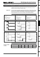
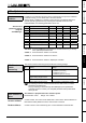
8.4.36 Output of variable voltage
The direct output of variable voltage is supported via the D/A monitor channels 0 to
3.
Addressable using parameters P76 (channel 2) and P77 (channel 3)
P76 Channel 2 X11/4
P77 Channel 3 X11/5
Resolution: 8 bit (incl. sign); corresponds to a resolution of 80 mV
Range: -10V...+10V
The calculation for output on the 8 bit channels 2 & 3 is as follows:
Parameter setting for required voltage U (-10V ... +10V)
P76 (P77) = 39 + Y (39,Y)
39: selection of voltage output
For positive voltage: Y = U * 0.0101067 / 10V
For negative voltage: Y = U * 0.0101067 / 10V + 0.0202134
(Note: set U negative in the 2nd formula)
-10.0V
+9.96V
0.0202134
0.0101067
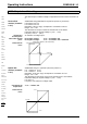
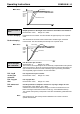
Addressable using P71 (channel 0) and P72 (channel 1)
P71 Channel 0 X17/1
P72 Channel 1 X17/2
Resolution: 12 bit (incl. sign); corresponds to a resolution of 5 mV
Range: -10V...+10V
The calculation for the output on the 12-bit channels 0 and 1 is as follows:
Parameter setting for required voltage U (-10V ... +10V)
P71 (P72) = Y
P73 (P74) = 39: selection of voltage output
Y = U * 101067 / 10V
-10.0V
+10.0V
0.010106
-0.0101067
Service D/A
monitor (channels
2 & 3):
Value before
decimal point:
Value after decimal
point:
Characteristic
curve:
Option D/A
monitor (channels
0 & 1):
Calculating the
output value:
Characteristic
curve:
POSA
POSR
SPEED
ACCEL
OUTPUT
Password
SPEED
SYNC
Mark
reference
POSR
SPEED
POSR
OUTPUT
Cam
controller
WAIT
GOTO
GOSUB
RETURN
END
REPEAT
IF I..
Comparison
WAIT Start
GOTO /
GOSUB EXT
IF Error/ Stop
Arithmetic
Position
monitoring
Idle display
Speed
monitoring
Engage /
disengage
brake / final
stage
Variable
voltage