
- Parker Compact Servo Controller User Guide
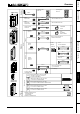


Interfaces
Process coupling using HEDA (Option A1 / A4)
171
Unit
hardware
Connector
assignment / cable
Technical dataConfigurationPositioning and
control functions
Optimization
functions
InterfacesAccessories /
options
StatusParameterError list
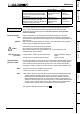
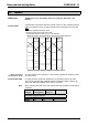
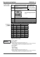
1st unit: Master Slave
Coupling of several cams with the
same time base and separate master
or slave oriented label synchronization
(see above)
COMPAX XX70
P184=42 (time base)
P188=42
COMPAX XX70
P188=42
P143
s
=P143
M
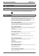
Linking of several cams with the same
time base and absolute zero drift
between the axes due to the transfer of
a position value (see above)
COMPAX XX70
P184=43 (scaled
master position)
P188=43
COMPAX XX70
P188=43
P143
s
=P143
M
Only position signals can be completely restored following HEDA transmission
errors . When transmitting velocities, transmission errors can lead to drift
tendencies between the axis positions. For this reason use of the position
values is preferred.
HEDA transmission or synchronization errors are errors E76, E77 and E78.
Synchronization is interrupted with E76, therefore an alignment is implemented
whereby the process position value is aligned in such a manner that a position leap
does not occur.
With E77/E78, the slave attempts to reach the new undisturbed process position
value in order to maintain the reference system.
Transmitting "VC" interrupts the synchronization.
Only activate "VC" when the unit is switched off.
When working with the user terminal BDF2, "VC" is transmitted when the
"Parameter edit" menu is exited.
Position values / position (P184=40/43/44/45): linear interpolation using old
values
Velocity values / frequencies (P184=42/46): retains old value
In cases when P188>0 on the master side, a fixed delay in the associated process
value is implemented, amounting to a total of 2 ms. This ensures that the master
waits until all axes have received the process value. This ensures that all axes,
including the master, continue to process the new nominal values simultaneously.
♦
Except for fast start, no additional I/O's are sent.
♦
There can be only one master on the bus!
♦
The position values for P184=44 and P184=45 are derived independently of the
current positioning operating mode (normal, continuous, reset). They are
obtained from the nominal position value and the actual position value and
made available in 24-bit format, as if with counter channels. This avoids jerky
changes in the start torque (in continuous mode) or when reading the end of the
curve (in reset mode). Only the lower 24 bits of these values are transmitted,
consisting of the resolver value and maximum 256 motor revolutions.
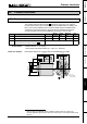
The required cable types are listed on Page 63.
Error handling
Error messages:
E76:
E77/E78:
Note!
Transmission error
procedure:
Synchronizing
process values:
Note:
Note: