
- Parker Compact Servo Controller User Guide


Start-up manual
COMPAX-M / -S
18
7.2.2 COMPAX-M system network, NMD10 / NMD20 mains module
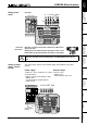
A COMPAX-M drive system consists of one mains module and one or more drive
controllers. The units are coupled with one another with flatband cables (see
below). These are arranged behind the front plate cover of the power unit and the
drive controller.
The power unit converts mains power (up to 3 * 500V AC) into DC current for the
intermediate circuit.
The two connectors for connection to the bus systems are located on the front
plate of the power unit. The connection assignment complies with the specifications
for 2-cable remote bus.
The 24V DC control voltage required by the system network is supplied from the
power unit.
A connector terminal on the front of the power unit is used for connecting the
control and status signals (EMERGENCY STOP, readiness) which you can
incorporate in the control of the entire system.
These signals and the bus lines are connected internally via a preformed
doublesided flatband cable. These cables are included with the drive controller.
The connectors which receive these connection cables are housed under the front
plate cover of the mains module and the drive controller.
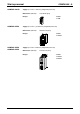
Attach a short circuit connector to the outgoing connector on the drive controller
that is furthest away from the mains module. The short circuit connector (order No.
102-908000) is included with the mains module.
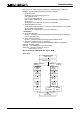
Installation arrangement
Before wiring up, always de-energize the unit.
Even once the mains supply has been switched off, dangerous
levels of voltage can remain in the system for up to 5 min.
The wires required for creating the system network are included in the delivery.
Open the front cover (upper section of front side) by loosening the top right knurled
screw and wire up the following:
!
24V DC voltage supply.
!
PE and DC current.
!
Emergency stop, ready and bus signals with a terminating connector on the last
unit.
From the mains module to the individual COMPAX-M.
When delivered, the terminating connector is located on the mains module.
HAUSER
COMPAX-M
DIGITAL
Status Number
X6
X8 X10
-+Enter
Ready Error
RS232
Input
Output
Test
Control
X9 X11
Value
HAUSER
COMPAX-M
DIGITAL
Status
Number
X6
X8
X10
-
+Enter
Ready
Error
RS232
Input
Output
Test
Control
X9
X11
Value
cable conduit
HAUSER
POWER SUPPLY
X6 X7
X8
Ready Error
RS485IN O UT
Control
power supply module
COMPAX-M COMPAX-M
main 24V motor
...
motor
L1 L2L3 PE 24V
+-
24V
+
-
PE
+LS
-LS
X1
X2
X3
X4
UVWPEbrake
PE+ -
X5
X1
X2
X3
X4
UVWPEbrake
PE+ -
X5
X1
X2
X3
X4
PE LS+ LS-
{
voltage supply
24V
emergency stop,
stand by and bus
signals
last device
equiped
with
terminal
plug
Short circuit
connectors
Wiring up the
system network