
- Parker Compact Servo Controller User Guide
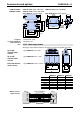


Accessories and options
COMPAX-M / -S
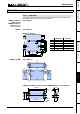
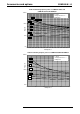
External ballast resistors
194
6
7,5
40
20
26
240
225
BRM8/01 is fitted with a 0.25m
connecting cable.
The maximum permitted length
is 2m.
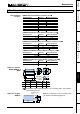
Danger!
Housing temperature may reach 200°C.
Dangerous voltage!
The device may only be used if completely fitted!
The external ballast resistances should be fitted so that contact protection is
provided.
The housing temperature of the ballast resistance may rise to 200°C depending
on the application.
Fit the connection lines underneath.
Observe the information on the resistances (warning signs).
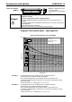
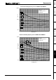
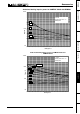
Diagrams: Brake pulse power - cooling period
Authorised braking impulse power with NMD20
100
1000
1
0000
0,0 0,2 0,4 0,6 0,8 1,0 1,2 1,4 1,6 1,8 2,0 2,2 2,4 2,6 2,8 3,0
Braking time / s
Pbdyn / W
F=50
F=5
F=10
F=2
F=1
F=0.5
F=100
F=20
For a braking time of 0.8s, a braking power of 700W is required.
The following can be determined from the diagram:
At the required magnitudes, this is between factor F=2 and factor F=5.
To maintain operating safety, select factor F=5; therefore the required cooling
down time equals:
Cooling down time = F * braking time = 5 * 0.8s = 4s
For a braking time of 0.3s, a braking power of 1000W is required.
The following can be determined from the diagram:
At the required magnitudes, this is between factor F=2 and factor F=5.
To maintain operating safety, select factor F=5; therefore the required cooling
down time equals:
Cooling down time = F * braking time = 5 * 0.3s = 1.5s
Dimension diagram:
BRM8/01
Example 1:
Example 2:
700W
F: Factor
Cooling down time = F *
braking time