
- Parker Compact Servo Controller User Guide


Start-up manual
COMPAX-M / -S
20
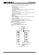
7.2.3 COMPAX-M dimensions/installation
The specific design of the COMPAX-M controller allows for wall installation
(distance: 61mm in COMPAX P1XXM and 86mm in larger units) in two different
ways.
Direct wall installation and dimensions of COMPAX-M and the mains
modules.
31
85
75
50
10
40
450
430
364
50
390
340
96
65
Attach with four 6-mm
hex-socket-head-screws
Status Number
X6
X8
X10
-
+
Enter
Ready Error
RS232
Input
Output
Test
Control
X9
X11
Value
DIGITAL
60
49
10
40
450
430
364
02XXM, 05XXM,
15XXM, NMD10
& NMD20
P1XXM
COMPAX-M
DIGITAL
Statu s Number
X8 X10
Enter
Ready Error
RS232
Input
Output
Test
Control
Value
COMPAX-M
Attach with two 6-mm
hex-socket-head-screws
65
The controllers are attached to the mounting plate with the back of the heat sink.
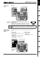
Indirect wall installation of COMPAX 02XXM, COMPAX 05XXM and COMPAX
15XXM and the mains modules NMD10 and NMD20.
50
50
82
424
408
Status Number
X6
X8 X10
-
+
Enter
Ready E rror
RS232
Input
Output
Test
Control
X9 X11
Value
DIGITAL
50
441,5
424
85
50
COMPAX-M
294
244 96
mounting
plate
mounting
plate
The heat sink is pushed back through a hole in the panel (on right of diagram). A
separate heat chamber is created between the installation plate and the rear wall
of the control cabinet. The angles required under designation MTS2 must be
complied with.
Indirect wall installation is not possible with COMPAX P1XXM.
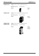
Units with fan:
COMPAX P1XXM, COMPAX 05XXM, COMPAX 15XXM
Units without fan: COMPAX 02XXM, NMD10, NMD20
Direct
wall installation:
Indirect
wall installation:
Fan configuration