
- Parker Compact Servo Controller User Guide


Additional COMPAX measuring quantites
211
Unit
hardware
Connector
assignment / cable
Technical dataConfigurationPositioning and
control functions
Optimization
functions
InterfacesAccessories /
options
StatusParameterError list
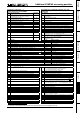
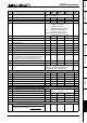
D/A monitor channels 0 ... 3
Status monitor S15 (P182); HEDA
Signal indicators (optimization display) S13 / S14
(P233/P234)
Selec-
tion
Measuring quantity Reference
value
Selec
tion
Meaning
17 Scaled transverse voltage
(For amplification of 1 use: 10V = 2 * ULS )
2 * ULS 17 Total number of HEDA transmission errors since beginning of
synchronization
18 Scaled longitudinal voltage
(For amplification of 1 use: 10V = 2 * ULS )
2 * ULS 18 Process nominal value HEDA
19 Host frequency 12/18 Mhz 2
-23
19 HEDA control word
20 Analogue HF1 CPX 70 / IPM
100%
≡
0.1V
20 HEDA status word
21 Analogue HF2 CPX 70 / IPM
100%
≡
0.1V
21 CPX X50 max. pos. synchronous lag error [units corresp. P90]
22 Master position (CPX 70)
M
T
≡
0.1 V
22 CPX X50 max. neg. synchronous lag error [units corresp. P90]
23 Slave nominal position (CPX 70)
S
T
≡
0.1 V
23 Output value of D/A monitor channel 1 (10V corresponds to 1)
24 Master speed (CPX 60, CPX 70)
2000min
-1
≡
1V
24 Output value of D/A monitor channel 2 (10V corresponds to 1)
25 25 Output value of service D/A monitor channel 3 (10V corresponds to 1)
26 26 Output value of service D/A monitor channel 4 (10V corresponds to 1)
27 27 External encoder position (units corresp. P90)
28 28 Measuring error (Difference between resolver position and external
encoder position in the unit corresponding to P90)
29 29 Effective motor load in % of the permissible motor continuous load
(from 100% = 1.1I
Nominal
E53 is indicated)
30 30
Effective unit load in % of the permitted continuous unit load (E53 is
displayed from 100%)
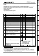
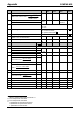
Meaning Variant: Reference values
31 Function pointer mark synchronization (range 0-7) 7x 10V = 2
23
32 Scaled correction factor 0 ... 1000 per thousands 7x 10V = 2
23
per thousands
33 Cycle counter X70 7x 10V = 2
23
cycles
34 DSP wait time [ms] 00,60,7x 10V = 2
23
ms
35 Digital inputs I1-I16 (range 0-2
16
) 00,60,7x 10V = 2
23
36 Status S16 (Bit 16...23) & digital outputs O1-O16 (Bit 0...15) 00,60,7x 10V = 2
23
37 Frequency encoder channel 4 [inc/ms] 60,7x 10V = 2
23
encoder increments/ms
38 Frequency encoder channel 5 [Inc/ms] (reserved) 10V = 2
23
encoder increments/ms
39 Constant value 0.00001 39 Cause of calculation error E07
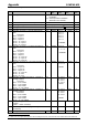
Meaning
40 Encoder position master channel 60,7x 10V = 2
23
encoder increments
41 Encoder velocity (reserved) 60,7x 10V = 2
23
encoder increments/ms
42 Internal time base of P35 7x 10V = 2
23
encoder increments/ms
43 Scaled master position 7x 10V = 2
23
encoder increments
44 Nominal position value in resolver increments 00,60,7x 10V = 128 motor revolutions
45 Actual position value in resolver increments 00,60,7x 10V = 128 motor revolutions
46 Differentiated resolver position 00,60,7x 10V = 2
22
increments/ms
47 47 Mark position (units corresp. P90) (COMPAX XX70)
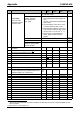
48 Bit 23...8: virtual inputs I33...I48
Bit 7...0: virtual inputs I32...I25
49 49
COMPAX 1000SL only
Bit 15...8: physical output status on X19/22...X19/15
Bit 7...0: physical input status on X19/9...X19/2
50
smoothed load torque (reference 200A)
50 P-component position controller (reserved)
51
Actual position S1 in physical units P90 (integral digit)
51 P-component speed controller (reserved)
52
Actual position S1 in physical units P90 (fractional digits)
52 I-component speed controller (reserved)
53 53 D-component speed controller (reserved)
44 54 P-component current controller (reserved)
55 55 I-component current controller (reserved)
56 56
Square of motor – peak current (reference value: 80 000A
2
)
45
57 57
from V5.61: square of the scaled resolver level (sin² + cos²);
reference value 1.0
<0.25 -> E42 (level error, 161) >1.0 -> E42 (limit error, 160)
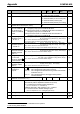
58 58
59 Depiction of status monitor
60 Sensor designation SinCos
61 Value read acyclically by S1 option
62 1st cyclic channel of S1 = position (100µs) (reference: 2
-24
revol.)
63 2nd cyclic channel of S1 (1 ms)
64 3rd cyclic channel of S1 (1 ms)
65 Absolute value from S2 option in format 12:12, limited to 0 ... P96
(reference: 1 revolution = 4096)
66 Absolute value from S1 option, not limited (reference: 2
-12
revolutions)
67 Additional error numbers with E42
68 Option designation / SW version number (S1 / S2 option)
69
70
71
72 from V5.14: sensor temperature SinCos (SR types only)
45
The peak value is deleted after 24V off/on or after shut down of the final stage (OTA≡1/2).