
- Parker Compact Servo Controller User Guide


Appendix
COMPAX-M/S
COMPAX standard parameters
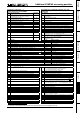
220
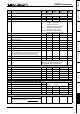
No. Meaning Unit
Minimum
value
Default
value
Maximum
value
Valid
from...
P216 Limit switch position E1 is approached when
...
"0": motor turns clockwise
"1": motor turns anti-clockwise
immediat.
P217 Limit switch mode "0": without limit switch
"1": with limit switch
(do not find during MZ)
"3": with limit switch
(find during MZ)
"5": with limit switch (without pos. locking)
immediat.
P218 Error cutout
Default value: P218=0 (E57 active)
Bit 0 ="0" E57 active ="1" E57 switched
off
immediat.
P219 Emergency stop
input on COMPAX-
M / Synchronous
STOP on COMPAX
XX00
=
0
no evaluation of emergency stop input on COMPAX-M
=7 emergency stop input on COMPAX-M active
=128 synchronous STOP on COMPAX XX0X without evaluation of
emergency stop input on COMPAX-M
=135 synchronous STOP on COMPAX XX0X with evaluation of
emergency stop input on COMPAX-M
VP
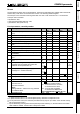
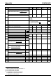
P221 Freely assign
standard inputs I1
...I8 with "1"
Input (valency) [Bit No.]: E1 (1) [1] •
••
• E2 (2) [2] •
••
• E3 (4) [3] •
••
• E4 (8) [4]
E5 (16) [5] •
••
• E6 (32) [6] •
••
• E6 (64) [7] •
••
• E6 (128) [8]
P221 = sum of valencies of all required free inputs.
The control functions are assigned to the fieldbus with the bit set (I17 ... I24)
immedia-
tely
P222 Freely assign
standard inputs I9
...I16 with "1"
Input (valency) [Bit No.]: I9 (1) [1] •
••
• I10 (2) [2] •
••
• I11 (4) [3] •
••
• I12 (8) [4]
I13 (16)[5] •
••
• I14 (32)[6] •
••
• I15 (64)[7] •
••
• I16 (128)[8]
P222 = sum of valencies of all required free inputs.
The control functions are assigned to the fieldbus with the bit set (I25 ... I32)
immedia-
tely
P223 Assign outputs O1 -
O8 to the OUTPUT
WORD command
with a "1"
Output (valency) [Bit No.]: O1 (1) [1] •
••
• O2 (2) [2] •
••
• O3 (4) [3] •
••
• O4 (8) [4]
O5 (16) [5] •
••
• O6 (32) [6] •
••
• O7 (64) [7] •
••
• O8 (128) [8]
P223 = sum of valencies of the OUTPUT WORD outputs
immedia-
tely
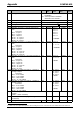
P224 Assign outputs O9
- O16 to the
OUTPUT WORD
62
command with "1"
Output (valency) [Bit No.]: O9 (1) [1] •
••
• O10 (2) [2] •
••
• O11 (4) [3] •
••
• O12 (8) [4]
O13 (16)[5] •
••
• O14 (32)[6] •
••
• O15 (64)[7] •
••
• O16 (128) [8]
P224 = sum of valencies of the OUTPUT WORD outputs
immedia-
tely
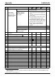
P225 Freely assign
standard outputs
with "1"
Output (valency) [Bit No.]: O1 (1) [1] •
••
• O2 (2) [2] •
••
• O3 (4) [3]
O4 (8) [4] •
••
• O5 (16) [5] •
••
• O6 (32) [6]
P225 = sum of valencies of all required free outputs.
immedia-
tely
P227 Assign special
functions to
outputs
Bit 1
63
="0": O2 is assigned the default function (=no warning).
Bit 1="1": O2 is assigned the "Idle monitor" function.
Bit 4="0": O5 is assigned the default function (position reached with
evaluation of P14)
Bit 4="1": O5 is assigned with the "O5 toggles when position
reached" function.
immedia-
tely
P229 Speed threshold for "Idle display" function (only
switched on if P227 bit 1="1")
‰ 0 0 255
VP
P232 Function I11 =0: I11 can be freely assigned
With external position adjustment switched on (P75>0):
=4: I11 switches the external position adjustment
(I11="0": off and I11="1": switched on)
COMPAX 1060/70SL: With analogue ±10V – interface
=4: I11 has the function "Enable analogue input
(
I11="0": Setpoint=0 I11="1": analogue input active)
VP
P233 Setting the optimization display S13 1...255
immedia-
tely
P234 Setting the optimization display S14 1...255
immedia-
tely
62
OUTPUT WORD – command is available with bus systems.
63
Bit-counting starts with Bit 0.