
- Parker Compact Servo Controller User Guide
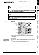
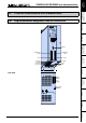

COMPAX 25XXS unit characteristics
COMPAX 25XXS connector and connection assignment
31
Unit
hardware
Connector
assignment / cable
Technical dataConfigurationPositioning and
control functions
Optimization
functions
InterfacesAccessories /
options
StatusParameterError list
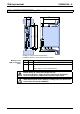
Before wiring up, always de-energize the unit.
Even once the mains supply has been switched off, dangerous
levels of voltage can remain in the system for up to 5 min.
When working with motors without a holding brake, the brake lines
must not be connected to COMPAX
The PE connection occurs with 10mm
2
under a fixing bolt
Caution!
If the unit has no control voltage, no displays will indicate that operating
voltage is present.
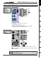
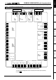
On unit side
X5 RS485 IN
X7
X2
X3
X1
X4
F19 3.16 AT
PE
L3
L2
L1
PE
N
L
3 x 230V AC
1 x 230V AC
AC
supply
+
-
24V DC
supply
RS485
OUT
motor and
motor brake
-
+
PE
W
V
U
PE
B
B
-
+
braking
resistance
connection for
external contact
for brake control
brake
+
-
PE
W
V
U
black 5
black 4
green/yellow
black 3
black 2
black 1
X1
sheetshielding of motor cable
2
3
0
V
A
C
2
3
0
V
A
C
230V AC
L1
L2
L3
max. 230V AC +10%
line to line voltage
!
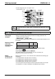
! Note the screened connection of the motor cable on the upper side of the unit.
! Clamp the motor cable with the open section of the screen braid under the
ground terminal.
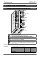
Motor side
! Via connectors.
The mains supply and control voltage supply are located on the upper side of the
unit.
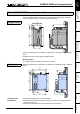
Power supply: there are 2 options (with the same output power):
3 * 80V AC - 3 * 250V AC
•
••
•
45-65Hz
•
••
•
fuse protection: 10A
1 * 100V AC - 1 * 250V AC
•
••
•
45-65Hz
•
••
•
Fuse protection: 16A
! Layout of contactors for the power supply:
Capacity according to device performanc: Application group AC3.
Wiring up motor
Wiring up mains
power / control
voltage