
- Parker Compact Servo Controller User Guide

Start-up manual
COMPAX-M / -S
32
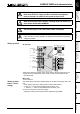
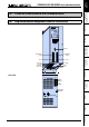
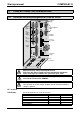
! Control voltage 24V DC ±10% ripple <1V
SS
Fuse protection: 16A
X4
PE
L3
L2
L1
PE
N
L
3 x 230V AC
1 x 230V AC
+
-
-
+
PE
W
V
U
PE
B
B
-
+
brake
resistance
1234
PE
L3
L2
L1
1234
PE
L
N
12
-
+
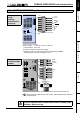
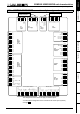
Connections for
3 x 230V AC
Connections for
1 x 230V AC
Bus system
X5 IN
X2
X3
X1
F19 3.16 AT
AC
supply
24V DC
supply
Bus system
X7 OUT
motor and
motor brake
24V control voltage
2
3
0
V
A
C
2
3
0
V
A
C
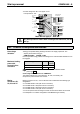
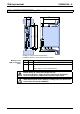
230V AC
L1
L2
L3
max. 230V AC +10%
line to line voltage
!
Note! Do not apply 3 * 400V AC.
Only wire up brake in motors with a holding brake! Otherwise, do not
wire up.
7.5.2 COMPAX 25XXS-specific technical data
! Energy recuperated during braking is stored in the supply capacitors. The
capacity and storable energy is:
COMPAX 25XXS: 1000 µ
µ µ
µF / 27 Ws
If the recuperated energy causes overvoltage, then external ballast resistances can
be engaged.
Braking power Duration
Cooling
down time
COMPAX 25XXS: ≤1.0 kW
unlimited
with Rext ≥ 56Ω: ≤2.5 kW
<2s
≥
10s
We can supply external ballast resistances for COMPAX 25XXS
(see Page 193).
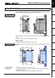
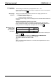
Connecting ballast resistance to COMPAX-S
The ballast resistance is connected to B+, B- and, if necessary, PE.
Output X4 is protected from short circuits.
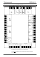
Mating connectors for X1,..X4 from Phoenix are included with the following type
designations:
X1: MSTB2.5/8/STF-5.08 (with screw connection)
X2: MSTB2.5/4/ST-5.08 (without screw connection)
X3: MSTB2.5/2/ST-5.08 (without screw connection)
X4: MSTB2.5/3/STF-5.08 (with screw connection)
You can acquire Phoenix housings for these connectors and these can be used
once adapted to our cables. Designation: KGG-MSTB2.5/(pin number).
Overvoltage
limitation
Maximum braking
power with
external ballast
resistance
Mating
connectors X1,
X2, X3 and X4