
- Parker Compact Servo Controller User Guide

COMPAX 45XXS/85XXS unit characteristics
COMPAX 45XXS/85XXS-specific wiring
37
Unit
hardware
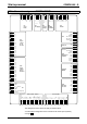
Connector
assignment / cable
Technical dataConfigurationPositioning and
control functions
Optimization
functions
InterfacesAccessories /
options
StatusParameterError list
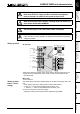
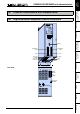
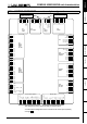
7.6.3 COMPAX 45XXS/85XXS-specific wiring
PE
L1
L2
L3
400V -
line
1234 756
R
D
HV:
1
T
D
High vol-
tage DC
1
Enable internal ballast resistor
X2
HV
T
D
L1
L2
L3
X5 IN
X7 OUT
R
D
X2
Bus system
X2
HV: DC current output
!
Power supply: 3 * 80V AC - max. 3 * 500V AC
Fuse protection: max. 16A
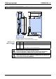
! Layout of contactors for the power supply
♦
Capacity according to device performance: Application group AC3
Control voltage: 24V DC ±10% ripple <1V
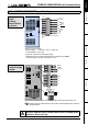
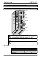
SS
-
BR1
W
V
U
ISOL 0V
Motor
Outputs
Enable -
Enable +
24V Input
24V GND
123456
Brake
+
-
PE
W
V
U
black 5
black 4
green/yellow
black 3
black 2
black 1
X1
Sheetshielding of
motor cable
Enable
Enable
+24V DC
0V
1234
X3
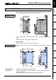
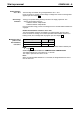
WARNING
Risk of electric shock
If case is not erthed
Connenct earth
before connecting supply
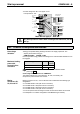
X1
Note the screened connection of the motor cable on the lower side of the unit.
Clamp the motor cable with the open section of the braided screen under the
ground terminal.
Only wire up brake lines in motors which have a holding brake.
Otherwise, do not wire up.
Wiring up mains
power /
enabling
internal ballast
resistance
Wiring up motor
/ control voltage
/ enable