
- Parker Compact Servo Controller User Guide

Start-up manual COMPAX-M / S
40
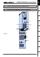
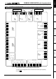
7.7 COMPAX 1000SL Unit characteristics
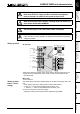
7.7.1 Connector and terminal assignment for COMPAX 1000SL
Fieldbus In
Encoder
Input / Output
Resolver
Fieldbus Out
Limit Switch
24 V DC
R
Dump
H2
H1
RS232
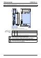
X6X5X13
X12
X17
X19
X2
X1 X4 X3
X14 X15
HEDA Out HEDA In
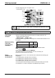
Input
+-
L1 N PE
UV
W
PE + -
Motor
Brake
PE
+
-
230 V AC
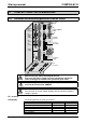
COMPAX - SL
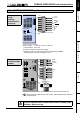
X7
X13
encoder
X6 RS232
X7 OUT
X5 IN
bus
systems:
X19 in-/
output
X14/X15
HEDA
X17
initiators
X12
resolver
X3 24V DC
supply
X4 ballast
resistance
X1 motor /
motor brake
X2 230V AC
supply
PE -
connection
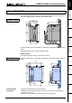
Before wiring up, always de-energize the unit.
Even once the mains supply has been switched off, dangerous
levels of voltage can remain in the system for up to 5 min.
When working with motors without a holding brake, the brake lines
must not be connected to COMPAX
Caution!
If the unit has no control voltage, displays will not indicate if operating
voltage is present.
at least 2.5mm
2
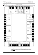
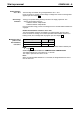
The following statuses are shown by the LEDs.
Status Red LED (H2) Green LED (H1)
24V not available off off
24V are switched on, boot up on off
Unit OFF off blinking
Unit error; drive switched off on blinking
Unit error; drive powered on on
Unit RUNNING off on
PE – terminal:
LED display
(Option)