
- Parker Compact Servo Controller User Guide

COMPAX 1000SL Unit characteristics
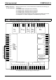
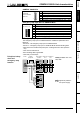
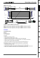
Connector and terminal assignment for COMPAX 1000SL
41
Unit
hardware
Connector
assignment / cable
Technical dataConfigurationPositioning and
control functions
Optimization
functions
InterfacesAccessories /
options
StatusParameterError list
Fieldbus InEncoder
Input / Output
Resolver
Fieldbus Out
Limit Switch
24 V DC
R
Dump
H2
H1
RS232
X6X5X13
X12
X17
X19
X2
X1 X4 X3
X14 X15
HEDA Out HEDA In
Input
+-
L1 N PE
UV
W
PE + -
Motor
Brake
PE
+
-
230 V AC
COMPAX - SL
X7
123
PE
L
N
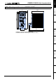
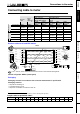
X2 230V AC supply
12
-
+
24V control voltage
brake
+
-
PE
W
V
U
black 5
black 4
green / yellow
black
3
black 2
black 1
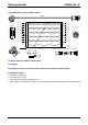
X1 motor / motor brake
PE
-
+
green / yellow
X4 ballast resistance
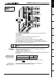
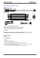
sheetshielding of motor cable
! Clamp the motor cable with the open section of the screen braid under the
ground terminal.
! Power supply:
1*100V AC - 1*250V AC • 45-65Hz • Fuse protection: 10A
! Layout of contactors for the power supply
Capacity according to device performance: Application group AC3
! Control voltage 24V DC ±10% ripple <1V
SS
• Fuse protection: max. 16A
The screen clamp for the screen connection of the motor cable is included and
must be screwed on in the illustrated position.
Only wire up brake in motors with a holding brake! Otherwise, do not
wire up.
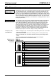
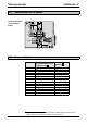
! Energy recuperated during braking is stored in the supply capacitors. The
capacity and storable energy is:
COMPAX 10XXSL: 660 µ
µ µ
µF / 17 Ws
If the recuperated energy causes overvoltage, then external ballast resistances can
be engaged.
Braking power Duration
Cooling
down time
COMPAX 10XXSL: ≤ 1.6kW
unlimited
We provide external ballast resistances for COMPAX 1000SL
(see Page 193).
The ballast resistance is connected to B+, B- and, if necessary, PE.
Output X4 is protected against short circuiting.
Unit wiring
COMPAX
1000SL
Overvoltage
limitation
Maximum braking
power with external
ballast resistance
Connecting the
ballast resistance