FITTERS INSTRUCTIONS OFFBEAT 3000 DL BUILT IN OVEN AND GRILL UNIT G.C. Number 11-477-21 INSTALLATION AND SERVICING INSTRUCTIONS THIS APPLIANCE I§ FOR USE ON NATURAL GAS ONLY AND CANNOT BE USED ON ANY OTHER GAS.
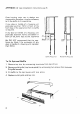
APPENDIX ‘A’ {see installation instructions page 5} Oven housing units vary in design ang construction therefore it may be necessary 1o fit the baffle to the appliance. If any door or handle of 8 housing unit protrudes less than 18mm in front of the grant face of the appliance then no battle is required If any doer or handle of 3 housing unit protrudes between 15mm and 50mm in front of the front face of the appliance then this baffle should be fitted.
TECHNICAL DATA DIMENSIONS Height Width Depth Overall 1196.5mm (47.17) 596mm (23.47) B60Tmm (2377 Minimum Cabinet 1150mm (463" B62mm (22.17) $B0mm (21.77) Weight of Appliance 78.6 kg (166 Ib) Minimum clearance top of appliance t roof of cabinet 10mm (0.47) CONNECTIONS Gas L. H.sideof appliance above grill Rc (1" behind control panel. Electrical Rear of appliance at bottom R.H. side 240V fused to amp.
IMPORTANT ~ SAFETY REQUIREMENTS This appliance must be installed in accordance with the Gas Safety Regulations and the relevant building regulations. Detailed recommendations are contained in the following British Standard Codes of Practice BS.6172: 1982, BS.5440:2 and CP331-3. PROVISION FOR VENTILATION The room commissioning the appliance should have an air supply in accordance with BS.
. Fix the cabinet securely to the wall making sure that it is level. 7. Check whether it is necessary to fit heat baffle by referring to Appendix “A' (page 2) fit baffle if necessary. 8. Untapped and remove bottom trim. Thread cable through notch already cut to the socket position. 800 myp, Fig. w08 Y nd This dimension refers 10 the . front fixing hole centers and Fig. 16 NOT the front s cont res.
9. Remove bottom louver by removing two screws situated between louvers. 10. Two people will be beaded to lift the appliance and it should be filled in by hooding under the oven base, ensuring that the pipe enters the rear an(: that the cable is not trapped by the unit. Push unit back as far as it will go. 11, Adjust front leveling screws until runner studs are in line with the slots in the front location plates, push unit fully home and fit nuts and washers to rummer studs — do not tighten. (See Fig. 2).
3. Connection to Electricity Supply WARNING THIS APPLIANCE MUST BE EARTHED. DO NOT EARTH THIS APPLIANCE TO THE GAS SUPPLY PIPING. This appliance must be connected to 240V A.C. 80Hz electricity supply which incorporates a 3 amp fuse. The appliance is supplied with two meters amp 3-core cable. If this proves to be insufficient to allow the appliance to be plugged into the nearest supply socket, the supply cable can be either: — {1} Replaced totally by a longer cable.
6. 10 Rotisserie Plug cooker in to mains electricity then depress and reseals the rotisserie switch. Check that tha rotisserie neon illuminates and that the rotisserie is operative, Oven Light Depress and release the oven light switch, Check that the oven light neon illuminates and that the light is operative. Changing door from L.H. to R.H.
Checking the Oven Contrails (Fig. 8) General Note: The automatic oven is controlled by a Normally Closed Solenoid Valve which is controlled by the clock and is only in operation during the cooking period. There is 8 manual override fitted to the solenoid valve for use in the event of a power failure, The operating fever is located between the louvers of the air inter gritter and can be pulled forward to supply gas to the oven for a temporary period unit the electricity supply is restored. {See Fig. 6.
9. 12 Automatic Operation 1. Having set the time of day display as described above, tur the auto/manual knob marked fulfill] into the horizontal position (auto} to point towards the 8] symbol. The word ‘AUTO’ should now flash on and off, 2. Press cooking period button marked BB, and 0.00 should show; while holding button rotate right-hand knob clockwise to read 0.02, this is a 2 minute cooking period. 3. Release push button to once again show the time of day.
FAULT FINDING KEY TO PARTS Proms RN Rotisserie Motor Oven Eight Firmer Display Timer Gantry Oven Light Neon Rotisserie Neon Oven Light Switch Rotisserie Switch Oven Thermostat Switch Grill Tap $witch Solenoid Valve Ignite Mains Input COLOR CODE b, Blue br. Brown bk, Black or. Orange w. White v.
Functional Flow Wiring Diagram FILL TAP SWITCH OVEN LIGHT SWITCH ) ROTISSERIE SWITCH —op—c : Siren o sou ens NITER )—i/ OVEN LIGHT OVEN LIGHT NEON ROTISSERIE NEON
Rotisserie b »N f ROTISSERIE SWITCH ROTS x o Tor (b ROTISSERIE NEON Fig. 17A START Hack correctional to YES Ass motor YES Motor is rotisserie motor terminals now quark ? satisfactory. Check wiring to motor and Exchange rotisserie ensure satisfactory. Check motor. ali contacts clean and tight Check rotisserie switch, Procedure Page 17. Disconnect and rectify any fault. Oven Light OVEN LIGHT SWITCH OVERNIGHT OVEN LIGHT NEON Fig.
SPARE PARTS ey G.C, Pert Number Makers' Somber Numbs Description off Ember 1 009 827 Appomattox Trim Assembly 2 43133 2 008 828 Outlet Grill Assembly 1 43134 6 008 829 Upright Trim L.H. Assembly 1 47097 7 009 830 Upright Trim R H.
SERVICING NOTES DISCONNECT ELECTRICITY SUPPLY BEFORE SERVICING NOTE: Turn off gas supply before servicing any gas carrying components. After servicing turn on gas and check for gas soundness. After satisfactory servicing ensure that the serviced components operate correctly. A, Removal of Control Panel . Disconnect from electricity supply. . Open grill road. . Pull off the twa control knob assemblies (Including springs). . Remove the two screws at the base of the control panel (See Fig. 18}, .
B1. Oven Door Removal 1. On opening the door two screws are seen on the bottom hinge screwed into the door. Remove these two, then do the same for the top while holding the door itself. 2. Remove the door leaving the hinges screwed to the oven, (See Fig. 18). B2. Oven Door Replacement 1. Rest the door on the bottom hinge and screw in place the top hinge. 2. Screw door to bottom hinge. B3.
B4, Dismantling Oven Door For exchange or removal of inner/outer panel and door handle (Fig. 20). 1. NOTARY a Remove oven door as detailed in Section BT, Lay it face down on s suitable fiat surface or the kitchen floor, . Remove the four screws on the inside of the door. . Lift off the inner door pans, and the inner glass panel. . The door handle retaining screws and the inner glass panel are now visible, . Remove the two overdrive screws which hold the handle. . The handle can now be removed. .
B5. Oven Door Seal Replacement The oven door seal is in three parts all with the same type of fixing, 1. The side sections are removed by pulling the seal away from oven door near to the bottom unit it disengages the hole in the oven door, then unhook seal at the top. . The top section is removed in the same manner as the sides. Slide the rubber seals off their dormers and then slide new seals onto the same dormers. . Re-assemble new door seals in reverse order, ensuring they are fitted as shown in Fig.
D. Oven Thermostat/Microswitch D1. Thermostat Removal Disconnect from electricity and turn off gas supply. Remove grill shelf, rear loose liner and loose liner from R.H. side of grit compartment, Remove panel on R.H. side by undoing the two overdrive screws at the top and bottom of the front edge. . Remove loose liners from oven. . Remove control panel {See Section "A’) and rest on grill door, . Remove plate and springs from controls; remove screw from RH.
D2. To Clean or Replace By-Pass Screw Remove control pane. {See Section Remove plate and springs from controls and remove screw from R H. end of switch insulation to aglow access. Remove by-pass screw located on the underside of the thermostat body using 2 4 BA spanner and clean or replace as required. Re-assemble in reverse sequence, ensuring the by-pass screw ‘O’ ring is sound and correctly located on the by-pass screw. Check for leaks before replacing control panel. D3.
4. Remove the tap from the gas rail after removing the two securing screws. NOTE: There is a gasket between the tap and the gas rail, 5, Replace in reverse order. 6. Check for leaks before replacing control panel. NOTE: Care should be taken to align tap spindle, control panel and bezel rings. E2. Grill Micro switch Removal 1. Remove control panel. {See Section 'A’) 2. Remove plate and springs from controls, and remove screw from R.H. end, of switch insulation to allow access. 3.
G. To Change Flame Failure Device 1. Disconnect from electricity supply. 2. Open bottom cupboard doors or drawer. 3. Remove bottom trim by unscrewing two screws from bottom flange, and remove bottom louver {inlet grille) by removing two screws from between louvers, taking care of the manual override lever. . Remove screws from front edge of electrics tray — ease tray forward and hang over front edge, using the two hooks provided. .
From inside of oven remove two screws and washers {each side of burner aperture) while supporting burner from below. Ease churner assembly and forward so that the naive is clear of the front of the appliance. Hold F.F.D. firmly and unscrew solenoid valve, being careful not to strain flame failure device capillary. . Transfer solenoid mounting plate note new encircled valve, . Re-assemble in reverse order, and check for leaks before fitting bottom louver. Change Clock Assembly .
g 11. Remove bracket with insulation from back of control panel (three screws). 12. Lift out lock and replace in reverse order, making sure that the spigot on clock face locates into respective hole in glass panel, NOTE: (A) To ease assembly the new ribbon harness needs to bs straightened out by laying fiat throughout its length.
L. To Replace Oven Light Bulb 1. Disconnect from electricity supply. 2. Open oven door and remove oven shaves. 3. Remove loose liners. 4. Insert a broad screwdriver bide between the oven back and the rear of the lens heat seal. Support the lens and pries the lens and heat seal forward sufficiently to release the spring clip fixing. Remove the lens complete with heat seal and clips. . Unscrew the bulb and discard. . Fit new 200/260V ~ 40 watt bulb. . Re-assemble in reverse order. oo M.
N. Changing the Spark Generator 1. Repeat operations 1-4 of Section "G’ and uncle tray cover from supply cable, . Disconnect the two H.T. leads. . Pull off harness edge connector block from spark generator board. . Squeeze sate spark generator board clip as shown {see Fig. 30) and lift the spark generator upwards. This will release the generator from its mounting clips. Discard generator . Fit new spark generator and ensure that H.T. leads are fitted to correct terminals — Oven to O — Grill to G, .
Q. To Change Grill HT. Lead Repeat operations 1-3 of Section ‘0" . Repeat operations 1-4 of Section ‘G . Remove grill electrode by undoing two fixing screws. . Underlip H.T. lead from spark board. . Uncle H.T. lead from grill electrodes and pull H.T. lead from appliance. . Fit new lead to electrode and re-thread through electrode hole and down bendy tube guide. Re-assemble in reverse order. Check spark gap (Fig. 31) and check ignition is satisfactory. Replace Oven Electrode Q Open oven door.
T. To Removes Rotisserie Motor NOTE: it is advisable to block oven boomer aperture with a suitable rag prevent screws falling through 1o bottom compartment . Disconnect from electricity supply. . Remove oven shelves and liners. . Removal the 1wo overdrive screws securing cover plate on oven back panel. . Support the motor assembly and remove the two pozidiv screws now exposed, Ease the mayor assembly forward and rest in the oven.
V. To Change Major Wiring Harass Remove control panel (See Section Repeat operations 2-4 of Section "G, Disconnect all leads except for: (a} H.T.leads. {b) Minor harness Reads, i.e. leads routed to rear top of appliance. Uncle harness from top and bottom side panels and withdraw. Thread new harness down between left-hand side panel and grill compartment. NOTE: To ease re-threading of harness, ths L M.
b blue or orange Y bellow br brown g green bk black w white KEY TO PARTS 1 rotisserie motor 2 oven light 6 rotisserie neon 10 grill taps timer display oven light sw il sol valve timer control 8 rotisserie sw 12 ignite 5 oven light neon 9 oven stat sw 13 mains input MOE FAT GAS APPLIANCES LTD. Angel Road, Edmonton, London N18 3HL Drawing No.
FITTERS INSTRUCTIONS OFFBEAT 3000 DL BUILT IN OVEN AND GRILL UNIT G.C. Number 11-477-21 INSTALLATION AND SERVICING INSTRUCTIONS THIS APPLIANCE I§ FOR USE ON NATURAL GAS ONLY AND CANNOT BE USED ON ANY OTHER GAS.
APPENDIX ‘A’ {see installation instructions page 5} Oven housing units vary in design ang construction therefore it may be necessary 1o fit the baffle to the appliance. If any door or handle of 8 housing unit protrudes less than 18mm in front of the grant face of the appliance then no battle is required If any doer or handle of 3 housing unit protrudes between 15mm and 50mm in front of the front face of the appliance then this baffle should be fitted.
TECHNICAL DATA DIMENSIONS Height Width Depth Overall 1196.5mm (47.17) 596mm (23.47) B60Tmm (2377 Minimum Cabinet 1150mm (463" B62mm (22.17) $B0mm (21.77) Weight of Appliance 78.6 kg (166 Ib) Minimum clearance top of appliance t roof of cabinet 10mm (0.47) CONNECTIONS Gas L. H.sideof appliance above grill Rc (1" behind control panel. Electrical Rear of appliance at bottom R.H. side 240V fused to amp.
IMPORTANT ~ SAFETY REQUIREMENTS This appliance must be installed in accordance with the Gas Safety Regulations and the relevant building regulations. Detailed recommendations are contained in the following British Standard Codes of Practice BS.6172: 1982, BS.5440:2 and CP331-3. PROVISION FOR VENTILATION The room commissioning the appliance should have an air supply in accordance with BS.
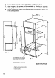
6. Fix the cabinet securely to the wall making sure that it is level. 7. Check whether it is necessary to fit heat baffle by referring to Appendix “A' (page 2) fit baffle if necessary. 8. Untapped and remove bottom trim. Thread cable through notch already cut to the socket position. 800 myp, Fig. w08 Y nd This dimension refers 10 the . front fixing hole centers and Fig. 16 NOT the front s cont res.
9. Remove bottom louver by removing two screws situated between louvers. 10. Two people will be beaded to lift the appliance and it should be filled in by hooding under the oven base, ensuring that the pipe enters the rear an(: that the cable is not trapped by the unit. Push unit back as far as it will go. 11, Adjust front leveling screws until runner studs are in line with the slots in the front location plates, push unit fully home and fit nuts and washers to rummer studs — do not tighten. (See Fig. 2).
3. Connection to Electricity Supply WARNING THIS APPLIANCE MUST BE EARTHED. DO NOT EARTH THIS APPLIANCE TO THE GAS SUPPLY PIPING. This appliance must be connected to 240V A.C. 80Hz electricity supply which incorporates a 3 amp fuse. The appliance is supplied with two meters amp 3-core cable. If this proves to be insufficient to allow the appliance to be plugged into the nearest supply socket, the supply cable can be either: — {1} Replaced totally by a longer cable.
6. 10 Rotisserie Plug cooker in to mains electricity then depress and reseals the rotisserie switch. Check that tha rotisserie neon illuminates and that the rotisserie is operative, Oven Light Depress and release the oven light switch, Check that the oven light neon illuminates and that the light is operative. Changing door from L.H. to R.H.
Checking the Oven Contrails (Fig. 8) General Note: The automatic oven is controlled by a Normally Closed Solenoid Valve which is controlled by the clock and is only in operation during the cooking period. There is 8 manual override fitted to the solenoid valve for use in the event of a power failure, The operating fever is located between the louvers of the air inter gritter and can be pulled forward to supply gas to the oven for a temporary period unit the electricity supply is restored. {See Fig. 6.
9. 12 Automatic Operation 1. Having set the time of day display as described above, tur the auto/manual knob marked fulfill] into the horizontal position (auto} to point towards the 8] symbol. The word ‘AUTO’ should now flash on and off, 2. Press cooking period button marked BB, and 0.00 should show; while holding button rotate right-hand knob clockwise to read 0.02, this is a 2 minute cooking period. 3. Release push button to once again show the time of day.
FAULT FINDING KEY TO PARTS Proms RN Rotisserie Motor Oven Eight Firmer Display Timer Gantry Oven Light Neon Rotisserie Neon Oven Light Switch Rotisserie Switch Oven Thermostat Switch Grill Tap $witch Solenoid Valve Ignite Mains Input COLOR CODE b, Blue br. Brown bk, Black or. Orange w. White v.
Functional Flow Wiring Diagram FILL TAP SWITCH OVEN LIGHT SWITCH ) ROTISSERIE SWITCH —op—c : Siren o sou ens NITER )—i/ OVEN LIGHT OVEN LIGHT NEON ROTISSERIE NEON
Rotisserie b »N f ROTISSERIE SWITCH ROTS x o Tor (b ROTISSERIE NEON Fig. 17A START Hack correctional to YES Ass motor YES Motor is rotisserie motor terminals now quark ? satisfactory. Check wiring to motor and Exchange rotisserie ensure satisfactory. Check motor. ali contacts clean and tight Check rotisserie switch, Procedure Page 17. Disconnect and rectify any fault. Oven Light OVEN LIGHT SWITCH OVERNIGHT OVEN LIGHT NEON Fig.
SPARE PARTS ey G.C, Pert Number Makers' Somber Numbs Description off Ember 1 009 827 Appomattox Trim Assembly 2 43133 2 008 828 Outlet Grill Assembly 1 43134 6 008 829 Upright Trim L.H. Assembly 1 47097 7 009 830 Upright Trim R H.
SERVICING NOTES DISCONNECT ELECTRICITY SUPPLY BEFORE SERVICING NOTE: Turn off gas supply before servicing any gas carrying components. After servicing turn on gas and check for gas soundness. After satisfactory servicing ensure that the serviced components operate correctly. A, Removal of Control Panel . Disconnect from electricity supply. . Open grill road. . Pull off the twa control knob assemblies (Including springs). . Remove the two screws at the base of the control panel (See Fig. 18}, .
B1. Oven Door Removal 1. On opening the door two screws are seen on the bottom hinge screwed into the door. Remove these two, then do the same for the top while holding the door itself. 2. Remove the door leaving the hinges screwed to the oven, (See Fig. 18). B2. Oven Door Replacement 1. Rest the door on the bottom hinge and screw in place the top hinge. 2. Screw door to bottom hinge. B3.
B4, Dismantling Oven Door For exchange or removal of inner/outer panel and door handle (Fig. 20). 1. NOTARY a Remove oven door as detailed in Section BT, Lay it face down on s suitable fiat surface or the kitchen floor, . Remove the four screws on the inside of the door. . Lift off the inner door pans, and the inner glass panel. . The door handle retaining screws and the inner glass panel are now visible, . Remove the two overdrive screws which hold the handle. . The handle can now be removed. .
B5. Oven Door Seal Replacement The oven door seal is in three parts all with the same type of fixing, 1. The side sections are removed by pulling the seal away from oven door near to the bottom unit it disengages the hole in the oven door, then unhook seal at the top. . The top section is removed in the same manner as the sides. Slide the rubber seals off their dormers and then slide new seals onto the same dormers. . Re-assemble new door seals in reverse order, ensuring they are fitted as shown in Fig.
D. Oven Thermostat/Microswitch D1. Thermostat Removal Disconnect from electricity and turn off gas supply. Remove grill shelf, rear loose liner and loose liner from R.H. side of grit compartment, Remove panel on R.H. side by undoing the two overdrive screws at the top and bottom of the front edge. . Remove loose liners from oven. . Remove control panel {See Section "A’) and rest on grill door, . Remove plate and springs from controls; remove screw from RH.
D2. To Clean or Replace By-Pass Screw Remove control pane. {See Section Remove plate and springs from controls and remove screw from R H. end of switch insulation to aglow access. Remove by-pass screw located on the underside of the thermostat body using 2 4 BA spanner and clean or replace as required. Re-assemble in reverse sequence, ensuring the by-pass screw ‘O’ ring is sound and correctly located on the by-pass screw. Check for leaks before replacing control panel. D3.
4. Remove the tap from the gas rail after removing the two securing screws. NOTE: There is a gasket between the tap and the gas rail, 5, Replace in reverse order. 6. Check for leaks before replacing control panel. NOTE: Care should be taken to align tap spindle, control panel and bezel rings. E2. Grill Micro switch Removal 1. Remove control panel. {See Section 'A’) 2. Remove plate and springs from controls, and remove screw from R.H. end, of switch insulation to allow access. 3.
G. To Change Flame Failure Device 1. Disconnect from electricity supply. 2. Open bottom cupboard doors or drawer. 3. Remove bottom trim by unscrewing two screws from bottom flange, and remove bottom louver {inlet grille) by removing two screws from between louvers, taking care of the manual override lever. . Remove screws from front edge of electrics tray — ease tray forward and hang over front edge, using the two hooks provided. .
From inside of oven remove two screws and washers {each side of burner aperture) while supporting burner from below. Ease churner assembly and forward so that the naive is clear of the front of the appliance. Hold F.F.D. firmly and unscrew solenoid valve, being careful not to strain flame failure device capillary. . Transfer solenoid mounting plate note new encircled valve, . Re-assemble in reverse order, and check for leaks before fitting bottom louver. Change Clock Assembly .
g 11. Remove bracket with insulation from back of control panel (three screws). 12. Lift out lock and replace in reverse order, making sure that the spigot on clock face locates into respective hole in glass panel, NOTE: (A) To ease assembly the new ribbon harness needs to bs straightened out by laying fiat throughout its length.
L. To Replace Oven Light Bulb 1. Disconnect from electricity supply. 2. Open oven door and remove oven shaves. 3. Remove loose liners. 4. Insert a broad screwdriver bide between the oven back and the rear of the lens heat seal. Support the lens and pries the lens and heat seal forward sufficiently to release the spring clip fixing. Remove the lens complete with heat seal and clips. . Unscrew the bulb and discard. . Fit new 200/260V ~ 40 watt bulb. . Re-assemble in reverse order. oo M.
N. Changing the Spark Generator 1. Repeat operations 1-4 of Section "G’ and uncle tray cover from supply cable, . Disconnect the two H.T. leads. . Pull off harness edge connector block from spark generator board. . Squeeze sate spark generator board clip as shown {see Fig. 30) and lift the spark generator upwards. This will release the generator from its mounting clips. Discard generator . Fit new spark generator and ensure that H.T. leads are fitted to correct terminals — Oven to O — Grill to G, .
Q. To Change Grill HT. Lead Repeat operations 1-3 of Section ‘0" . Repeat operations 1-4 of Section ‘G . Remove grill electrode by undoing two fixing screws. . Underlip H.T. lead from spark board. . Uncle H.T. lead from grill electrodes and pull H.T. lead from appliance. . Fit new lead to electrode and re-thread through electrode hole and down bendy tube guide. Re-assemble in reverse order. Check spark gap (Fig. 31) and check ignition is satisfactory. Replace Oven Electrode Q Open oven door.
T. To Removes Rotisserie Motor NOTE: it is advisable to block oven boomer aperture with a suitable rag prevent screws falling through 1o bottom compartment . Disconnect from electricity supply. . Remove oven shelves and liners. . Removal the 1wo overdrive screws securing cover plate on oven back panel. . Support the motor assembly and remove the two pozidiv screws now exposed, Ease the mayor assembly forward and rest in the oven.
V. To Change Major Wiring Harass Remove control panel (See Section Repeat operations 2-4 of Section "G, Disconnect all leads except for: (a} H.T.leads. {b) Minor harness Reads, i.e. leads routed to rear top of appliance. Uncle harness from top and bottom side panels and withdraw. Thread new harness down between left-hand side panel and grill compartment. NOTE: To ease re-threading of harness, ths L M.
b blue or orange Y bellow br brown g green bk black w white KEY TO PARTS 1 rotisserie motor 2 oven light 6 rotisserie neon 10 grill taps timer display oven light sw il sol valve timer control 8 rotisserie sw 12 ignite 5 oven light neon 9 oven stat sw 13 mains input MOE FAT GAS APPLIANCES LTD. Angel Road, Edmonton, London N18 3HL Drawing No.