INSTRUCTION BOOKLET GB i MIXED FUEL COOKER CSIM 509 Please read this instruction booklet before using the appliance
Important Safety Information You MUST read these warnings carefully before installing or using the appliance. If you need assistance, contact our Customer Care Department on 08705 950950 Installation l l l l l l This cooker must be installed by qualified personnel, according to the manufacturers instructions and to the relevant British Standards. This cooker is heavy. Take care when moving it. Any gas installation must be carried out by a registered CORGI installer.
Contents For the User For the Installer Important Safety Information 2 Instructions for the Installer 17 Description of the Cooker 3 Important Safety Requirements 18 Control Panel 4 Installation 19 Using the Hob 5 Electrical connections 21 Before the First Use of the Cooker 6 Commissioning 22 Electric Oven 6 Conversion from Natural to LPG Gas 23 Hints and Tips 7 Using the Fan Oven & Defrosting function 8 Fan Cooking Chart 9 Defrosting Chart 9 Grilling 10 Maintenance and C
Control Panel 1 NORMAL RAPID SIMMER SELECTOR NORMAL TEMPERATURE TIMER °c 0 0 50 15 20 40 0 20 150 5 6 Electric Ignition push button Back left burner control knob (semi-rapid) Front left burner control knob (ultra-rapid) Front right burner control knob (auxiliary) Back right burner control knob (semi-rapid) 6. 7. 8. 9. 7 35 4 30 1. 2. 3. 4. 5.
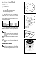
Using the Hob Hob burners F To light a burner: l l l l Push the electric ignition button which is marked with a little spark ( ). At the same time, push in and turn the relevant control knob anticlockwise to maximum position. Then adjust the flame as required. If the burner does not ignite, turn the control knob to zero, and try again. FO 2063 When switching on the mains, after installation or a power cut, it is quite normal for the spark generator to be activated automatically.
Before the First Use of the Cooker Remove all packaging, both inside and outside the oven, before using the appliance. Before first use, the oven should be heated without food. During this time, an unpleasant odour may be emitted. This is quite normal. 1. Switch the oven function control knob to fan cooking F . 2. Set the thermostat control knob to MAX. 3. Open a window for ventilation. 4. Allow the oven to run empty for approximately 45 minutes.
Using the Oven Always cook with the oven door closed. Stand clear when opening the drop down oven door. Do not allow it to fall open - support the door using the door handle, until it is fully open. The oven has four shelf levels, and is supplied with two shelves. The shelf positions are counted from the bottom of the oven as shown in the diagram. It is important that these shelves are correctly positioned as shown in the diagram. Do not place cookware directly on the oven base.
Using the Fan Oven & Defrosting function The air inside the oven is heated by the element around the fan situated behind the back panel. The fan circulates hot air to maintain an even temperature inside the oven. The advantages of cooking with this function are: l Faster Preheating As the fan oven quickly reaches temperature, it is not usually necessary to preheat the oven although you may find that you need to allow an extra 5-7 minutes on cooking times.
Fan Cooking Chart This chart is intended as a guide only. It may be necessary to increase or decrease the temperature to suit your individual requirements. Only experience will enable you to determine the correct setting for your personal requirements. Food Thermostat Runner Position Time Biscuits, cookies 2 trays 160-190 1-3 18-25 min. Bread, yeast doughs 2 trays 170-200 1-3 35-45 min. Cakes, Victoria sandwich 2 trays 160-170 1-3 20-28 min.
Grilling Grilling must be carried out with the oven door closed. The grill pan handles must be removed from the pan. FHow to Use the Grill 1. Turn the oven control function knob to . 2. Turn the thermostat control knob on the required temperature. 3. Adjust the grid and grill pan runner position to allow for different thicknesses of food. Position the food close to the element for faster cooking and further away for more gentle cooking.
Maintenance and Cleaning Before any maintenance or cleaning can be carried out, you must DISCONNECT the cooker from the electricity supply. The Hob Top The Pan Support The hob is best cleaned whilst it is still warm, as spillage can be removed more easily than if it is left to cool. The pan support is dishwasher proof. If washing it by hand, take care when drying it as the enamelling process occasionally leaves rough edges. If necessary, remove stubborn stains using a paste cleaner.
Oven Cavity The enamelled oven cavity is best cleaned whilst the oven is still warm. Wipe the oven over with a soft cloth soaked in warm soapy water after each use. From time to time it will be necessary to do a more thorough cleaning, using a proprietary oven cleaner. If the soilage has become set, after the oven has cooled down, the following process will help to soften the splatters to help make cleaning easier. F 1. Place the grill/ meat pan on the oven shelf positioned in the lowest runner. 2.
Something Not Working If the appliance is not working correctly, please carry out the following checks, before contacting your local Service Force Centre. IMPORTANT: If you call out an engineer to a fault listed below, or to repair a fault caused by incorrect use or installation, a charge will be made even if the appliance is under guarantee.
Service and Spare Parts Customer Care If you require spare parts or an engineer contact your local Service Force Centre by telephoning: 08705 929 929 Your call will be routed to the Service Force Centre covering your post code area. The addresses of Service Force Centres are detailed on the following pages.
To contact your local Service Force Centre telephone 08705 929 929 CHANNEL ISLANDS GUERNSEY Guernsey Electricity PO Box 4 Vale, Guernsey Channel Islands GY1 3AD JERSEY Jersey Electricity Company Haut De Lorme Rue De Haut De Lorme Trinity Jersey Channel Islands JE3 5FG ISLE OF LEWIS 54 Claremont Street Aberdeen AB10 6RA AUCHTERMUCHTY 33a Burnside Auchtermuchty Fife KY14 7AJ BLANTYRE DUMFRIES DUNOON EDINBURGH GLASGOWUnit 4 Unit 5 Block 2 Auchenraith Ind.
To contact your local Service Force Centre telephone 08705 929 929 LONDON & EAST ANGLIA MIDLANDS BIRMINGHAM 66 Birch Road East Wyrley Trading Estate Witton Birmingham B6 7DB BOURNE Pinfold Road Bourne PE10 9HT BRIDGNORTH 68 St.
Instructions for the Installer Technical Data Appliance Class 2 sub class 1 and Class 1 Appliance category: II 2H3+ Appliance gas supply: Natural Gas G20 20mbar Hob Rear left burner (semi-rapid) Front left burner (ultra-rapid) Rear right burner (semi-rapid) Front right burner (auxiliary) 2,000 W 3,500 W 2,000 W 1,000 W Oven Top heating element Bottom heating element Grill Element Convection heating element Convection fan Oven light Total rating Supply voltage (50 Hz) 1,045 W 1,250 W 1,880 W 2,090 W 30
Important Safety Requirements This appliance must be installed in accordance with the Gas Safety (Installation and Use) Regulations (current addition) and the I.E.E. Wiring Regulations. Detailed recommendations are contained in the following British Standard Codes of Practice - B.S. 6172, B.S. 5440: Part 2 and B.S. 6891: Current Editions. Provision for Ventilation The room containing the cooker should have an air supply in accordance with B.S. 5440: Part 2: Current Editions.
Installation Positioning the Appliance (Fig. 1) - - D C 115 E 420 - Note A: The appliance is designed to be flush fitted with 2mm clearance at each side to allow for it to be pulled forward for cleaning etc. Note B: The hotplate side trims should be flush with the cabinets and must not be below. Adjustable levelling feet at the front and rear are provided on the base of the appliance.
300 mm. WALL FACE BACK OF COOKER 100 mm. 580 mm. ENGAGEMENT EDGE FOR STABILITY BRACKET LEVELLING FEET BASE OF COOKER A ADJUSTABLE FOOT PENCIL LINE ON THE FLOOR 295 mm. SIDE VIEW OF THE COOKER PLAN VIEW OF THE COOKER FO 2601 Fig. 2 Fitting the Stability Bracket (Not supplied) If the cooker has to be installed with a flexible supply pipe, it is necessary that a stability device is fitted. (See "Important Safety Requirements").
Electrical connections Any electrical work required to install this cooker should be carried out by a qualified electrician or competent person, in accordance with the current regulations. THIS COOKER MUST BE EARTHED. Permanent Connection The manufacturer declines any liability should these safety measures not be observed. In the case of a permanent connection, it is necessary that you install a double pole switch between the cooker and the electricity supply (mains), with a minimum gap of 3 mm.
Commissioning When the hob has been fully installed it will be necessary to check the minimum flame setting. To do this, follow the procedure below. - Turn the gas tap to the MAX position and ignite. - Set the gas tap to the MIN flame position then turn the control knob from MIN to MAX several times. If the flame is unstable or is extinguished follow the procedure below. Procedure: Re-ignite the burner and set to MIN. Remove the control knob.
Conversion from Natural to LPG Gas IMPORTANT The replacement/conversion of the gas hob should only be undertaken by a CORGI registered engineer. It is important to note that this model is designed for use with natural gas but can be converted for use with butane or propane gas providing the correct injectors are fitted. The gas rate is adjusted to suit.
Grafiche MDM - Forlì CUSTOMER CARE Parkinson Cowan 55-77 High Street Slough Berkshire, SL1 1DZ Tel: 08705-950950 © Electrolux Household Appliances Limited 2001 From the Electrolux Group. The worlds No.1 choice. The Electrolux Group is the worlds largest producer of powered appliances for kitchen, cleaning and outdoor use. More than 55 million Electrolux Group products (such as refrigerators, cookers, washing machines, vacuum cleaners, chain saws and lawn mowers) are sold each year to a value of approx.