Habu 2 Instruction Manual • Bedienungsanleitung • Manuel d’utilisation • Manuale di Istruzioni
EN NOTICE All instructions, warranties and other collateral documents are subject to change at the sole discretion of Horizon Hobby, Inc. For up-to-date product literature, visit www.horizonhobby.com and click on the support tab for this product.
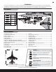
EN – Introduction – You are about to take flight with one of the hottest electric ducted fans ever built. Its potent one-two punch of speed and precision aerobatic ability will make every flight one to remember. Before you take to the sky though, you must read through this manual. The ParkZone® Habu 2 can cover a lot of ground in a hurry and things happen fast. The better understanding you have of its performance and systems prior to your first flight, the better that flight will be.
EN Low Voltage Cutoff (LVC) When a Li-Po battery is discharged below 3V per cell, it will not hold a charge. The ESC protects the flight battery from over-discharge using Low Voltage Cutoff (LVC). Before the battery charge decreases too much, LVC removes power supplied to the motor. Power to the motor pulses, showing that some battery power is reserved for flight control and safe landing. When the motor pulses, land the aircraft immediately and recharge the flight battery.
EN Arming the ESC Before Flight 1 • Lower throttle and throttle trim to lowest settings. 2 Power on Transmitter 3 • Connect battery to ESC. 4 • Power on ESC switch. Wait 5 seconds Continuous LED Series of tones Installing the Wing B A If you plan on installing optional flaps or retracts, you must do so before installing the wing. Please proceed to the following pages for instructions. 1. Remove the canopy from the fuselage. 2. Turn the wing and fuselage so their bottom sides face up. 3.
EN If you are assembling your aircraft using only stock parts, proceed to the Installing the Landing Gear section. Installing Optional Flaps 1. Install the left and right flap servos (A) (PKZ1081 x 2, sold separately) in the wing pocket using hot glue or double-sided tape. 2. Install the control horns (B) and plates (C) on the wing using 2 screws (D) in each horn. 3. Install a connector and clevis (E) in the second innermost hole of the servo arm and outer hole of the control horn. 4.
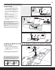
EN Installing the E-flite Optional Retractable Landing Gear Before installing the optional E-flite® retractable landing gear (EFLG110), collect the wheels and necessary fasteners from the included aircraft parts. 2 in (51mm) A Setting up the Retractable Nose Gear Strut For Your aircraft 1 in (25.4 mm) B The nose gear strut included with the electric retracts does not let the nose gear fully retract into the fuselage. Cut, then bend the nose strut so that the nose wheel extends and retracts freely.
EN Installing the E-flite Optional Retractable Landing Gear (Continued) 1. Measure and mark 2.25 inches (57.2mm) below the coil of the strut, then cut off the strut (A). 2. Install the included rear wheels (B) on the retract axles (C), using wheel collars (D) and set screws (E). 3. Loosely fit the retract axles on the rear landing gear struts (F) using the axle screws (G). 4. Ensure the wheels move freely in and out of the wheel wells when extending and retracting, then tighten the axle screws on the struts.
EN Installing the Fixed Landing Gear Nose Gear Installation J 1. Insert the nose strut (A) into the post in the nose gear plate (B) while aligning the flat spot on the strut with the set screw (C). The coil on the nose strut should be facing rearward. 2. Connect the nose gear linkage (D) to the innermost hole in the steering servo arm (E) in the fuselage. 3. Attach the clevis (F) to the outer most hole in the nose gear steering arm (G). 4.
EN Attaching the Tail 1. Loosely align the horizontal stabilizer unit (A) on the rear of the fuselage. 2. Correctly connect the rudder and elevator servo connectors to the marked connectors in the fuselage (B). B A NOTICE: Ensure no wires are pinched or damaged when the tail unit is attached to the fuselage. 3. Align and install the unit on the top of the rear fuselage using 2 screws (C).
EN Installing Clevises on Control Horns and Control Centering Tip: Turn the clevis clockwise or counterclockwise on the linkage. • Pull the tube from the clevis to the linkage. • Carefully spread the clevis and put the clevis pin into the desired hole in the control horn. • Move the tube to tighten the clevis onto the control horn. After binding a transmitter to the model receiver, set all trims and sub-trims to 0, then adjust the clevises by hand to center the control surfaces. 1. 4. 2. 5. 3. 6.
EN Control Direction Test Bind your aircraft and transmitter before performing these tests. Move the controls on the transmitter to ensure the aircraft control surfaces move correctly. After doing the Control Test, correctly set the failsafe. Make sure the transmitter controls are at neutral and the throttle and throttle trim are in the low position, then rebind the model to your transmitter.
EN Dual Rates We recommend using a DSM2/DSMX aircraft transmitter capable of dual rates. Adjust according to individual preferences after initial flight. 1/2 or Takeoff Flap Flap down Full Flaps 13mm down 25mm down Service of Power Components High Rate Low Rate Aileron 19mm up/down 13mm up/down Elevator 16mm up/down 13mm up/down Rudder 25mm left/right 19mm left/right MAINTENANCE Disassembly Assembly CAUTION: Always disconnect the flight battery before performing motor service. 1.
EN Preflight Checklist Before Flying Check List Before Flying Check List 1. Charge flight battery. 6. Adjust flight controls and transmitter. 2. Install flight battery in aircraft (once it has been fully charged). 7. Perform a radio system Range Check. 3. Bind aircraft to transmitter. 8. Find a safe and open area. 4. Make sure linkages move freely. 9. Plan flight for flying field conditions. 5. Perform Control Direction Test with transmitter.
EN Post Flight Checklist After Flying Check List 1. Disconnect flight battery from ESC (Required for Safety and battery life). 2. Power off transmitter. 3. Remove flight battery from aircraft. 4. Recharge flight battery. After Flying Check List 5. Repair or replace all damaged parts. 6. Store flight battery apart from aircraft and monitor the battery charge. 7. Make note of flight conditions and flight plan results, planning for future flights.
EN Troubleshooting Guide Problem Aircraft will not respond to throttle but responds to other controls Possible Cause Solution Throttle is not set to lowest stick postiion and/or throttle trim is too high Reset controls with throttle stick and throttle trim at lowest setting Throttle servo travel is lower than 100% Make sure throttle servo travel is 100% or greater Throttle channel is reversed Reverse throttle channel on transmitter Extra fan noise or extra vibration Damaged rotor and spinner, col
EN Limited Warranty What this Warranty Covers Inspection or Services Horizon Hobby, Inc. (“Horizon”) warrants to the original purchaser that the product purchased (the “Product”) will be free from defects in materials and workmanship at the date of purchase.
EN Contact Information Country of Purchase Horizon Hobby Address Phone Number/Email Address Horizon Service Center (Electronics and engines) 4105 Fieldstone Rd Champaign, Illinois 61822 USA 877-504-0233 Online Repair Request: visit www.horizonhobby.com/service Horizon Product Support (All other products) 4105 Fieldstone Rd Champaign, Illinois 61822 USA 877-504-0233 productsupport@horizonhobby.
© 2012 Horizon Hobby, Inc. ParkZone, Delta-V, DSM, DSM2, ModelMatch, Bind-N-Fly, EC3 and Z-Foam are trademarks or registered trademarks of Horizon Hobby, Inc. DSMX is a trademark of Horizon Hobby, Inc., registered in the U.S. The Spektrum trademark is used with permission of Bachmann Industries, Inc. Futaba is a registered trademark of Futaba Denshi Kogyo Kabushiki Kaisha Corporation of Japan. Patents Pending www.parkzone.