No.
4857 Reactor Controllers TABLE OF CONTENTS Module 2: Pressure Display and High Pressure Alarm Alarm Adjustment................................. 25 Related Instructions .............................2 Customer Service.................................2 Preface 3 Module 3: Tachometer Stirring Speed Adjustment ................... 26 Scope ...................................................3 Applications..........................................3 Explanation of Symbols........................
4857 Reactor Controllers PREFACE Scope Applications These instructions cover the installation and operation of Parr Model 4857 Process Controller as used with Parr Laboratory Reactors and Pressure Vessels. They cover the basic functions provided in each of these controllers. The users should study the instructions carefully before using any of these controllers so that they will fully understand the capabilities of this equipment and the safety precautions to be observed in its operation.
857 Reactor Controllers Explanation of Symbols I On position O Off position This CAUTION symbol may be present on the Product Instrumentation and literature. If present on the product, the user must consult the appropriate part of the accompanying product literature for more information. Protective Earth (PE) terminal. Provided for connection of the Protective Earth (green or green/yellow) supply system conductor. Safety Information Intended Usage To avoid electrical shock, always: 1.
4857 Reactor Controllers General Specifications Environmental Conditions Electrical Ratings: 115VAC 50/60 Hz 3.0 Amps 230VAC 50/60 Hz 3.0 Amps This instrument is to be used indoors and requires 3 square feet of space below the controller in a well-ventilated area with convenient access to an electric outlet.
4857 Reactor Controllers User’s Responsibility All standard Parr pressure vessels are provided with either a suitable relief device or a means to attach one (typically in the form of a plugged opening). When a pressure vessel is delivered without a pressure venting device, it is the customer’s responsibility to provide pressure relief in order to protect the operator and the equipment from destructive high pressures.
4857 Reactor Controllers INSTALLATION General Instructions The Auxiliary Temp connection is for a secondary thermocouple or RTD harness. Set the controller near the reactor on a sturdy bench or table where there is convenient access to an electrical outlet capable of carrying up to 20 amperes. Leave a space of at least twelve inches between the controller and the heater of the reactor so that the controller will not be affected by radiant heat. The Tachometer connection is for the optical sensor harness.
4857 Reactor Controllers SWITCHES AND INDICATORS PROTECTIVE FUSES 4857 Switches and Indicators 4857 Fuses The Main Switch is a manual, two-position, illuminated switch which will cut off power to the controller. The light indicates power the power is on. Take care to position the controller such that the main power switch may be accessed easily when the controller needs to be disconnected. Two instrument fuses are mounted on the back panel. These are Fast-acting, 250VAC, 3.
4857 Reactor Controllers MODEL 4857 PROCESS CONTROLLER SPECIFICATIONS Temperature Control Parameters To facilitate start up with reasonably good PID control parameters for heating and cooling, all 4857 Process Controllers are programmed at the factory with the temperature control settings shown on the right. Module 1: Temperature Control Cycle time 2 seconds Proportional Band 25 °C Integral Time 5 min Derivative Time 25 sec Output 1 on these controllers drives the heater.
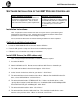
4857 Reactor Controllers SOFTWARE INSTALLATION OF THE 4857 PROCESS CONTROLLER Before Software Installation Minimum PC Requirements The CalGrafix software should be installed on a PC which has not previously been used to run software for Cal applications. The PC should meet at least the minimum system requirements. As a general requirement, we would recommend a minimum of Pentium 450MHz with 256MB RAM, WindowsTM 2000/XP and screen resolution, 1024 x 768.
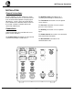
4857 Reactor Controllers Connections between single Reactor, 4857 Process Controller, and single 4875 Power Controller Diagram 1: Schematic Diagram of Connections to 4857 Process Controller for control of a single reactor with 4875 Power Controller - 11 -
4857 Reactor Controllers Connections between two Reactors, 4857 Process Controller, and dual 4875 Power Controllers Diagram 2: Schematic Diagram of Connections to 4857 Process Controller for control of two reactors with two 4875 Power Controllers - 12 -
4857 Reactor Controllers OPERATION OF THE 4857 PROCESS CONTROLLER Before operation Be certain to set the power settings on the PC such that it will not hibernate or time out after a period of time. After CalGrafix and the USB Drivers are installed on the PC, it is OK to attach the 4857 to the PC according to diagram 1 or diagram 2 and turn it on. Run the CalGrafix Program 1. The CalGrafix Program has been added to the program list.
4857 Reactor Controllers OPERATION OF THE 4857 PROCESS CONTROLLER (CONTINUED) Run the CalGrafix Program (continued) 4. A graphic of the 4857 Control Module will be displayed. The base module is illustrated in the center with modules 1-4 on either side. The 4857B will have two graphics displayed instead of one. 4857 Main Control Screen 5. The process may be controlled according to the instructions regarding operation of the individual modules.
4857 Reactor Controllers OPERATION OF THE 4857 PROCESS CONTROLLER (CONTINUED) Factory Defaults Restoring the 4857 to it factory defaults is relatively simple. There are is a file on the 521M CD which may be copied to the PC at "\Factory Defaults\factorydefaults.dev". Opening the .dev file with CalGrafix will restore the controller settings in the 4857 Process Controller. Restoring Factory Default Values 1. Set the active COM port to COM7.
4857 Reactor Controllers OPERATION OF THE 4857 PROCESS CONTROLLER (CONTINUED) Finding the Active COM Port When using CalGrafix to connect to the 4857 Process Controller, it is advantageous to know which COM port the PC is using to connect to the controller. The following instructions detail how to find the active COM port with Windows 2000 as the operating system. 1. Connect the 4857 to the PC using the provided cable and turn the 4857 on. 2.
4857 Reactor Controllers OPERATION OF THE 4857 PROCESS CONTROLLER (CONTINUED) Changing the Name of a Module 1. Right click on controller image. 2. Select properties and select "Properties >> Module 1", or whichever module you would like to change. 3. Expand "Module Settings". 4. Change the name from "Module 1" to another name such as "Temperature" and click OK.
4857 Reactor Controllers OPERATION OF THE 4857 PROCESS CONTROLLER (CONTINUED) Autotuning The 4857 Process Controller is equipped with default PID values from the factory designed to give reasonable temperature control across a wide temperature range. Autotuning is not recommended unless the system has exhibited poor control using the default PID values. The 4857 Process Controller may be auto tuned at setpoint. Using the other types of auto tune (not the tune at setpoint) will likely result in an error. 1.
4857 Reactor Controllers MODULE 1: TEMPERATURE CONTROL MODULE Setpoint Adjustment Before carrying out an autotune or run with the default settings to ensure the system is safe to operate at the setpoint value. 1. Right click on controller image. 2. Select properties and select programmer and set-points. 3. Expand (+) setpoints menu. 4. Enter Module 1 - Setpoint 1 value for the required module (click out of value box once setting entered to ensure value is accepted) 5. Apply setting and click OK 6.
4857 Reactor Controllers MODULE 1: TEMPERATURE CONTROL MODULE (CONTINUED) High Temperature Alarm Adjustment The high temperature alarm on Module 1 may also be adjusted. 1. Right click on controller image. 2. Select properties and select "Properties >> Module 1". 3. Expand "Module 1 - Setpoint 3 control". 4. Enter Module 1 - Setpoint 3 value for the required module (click out of value box once setting entered to ensure value is accepted) 5. Apply setting and click OK. 6.
4857 Reactor Controllers MODULE 1: TEMPERATURE CONTROL MODULE (CONTINUED) Changing PID Settings, Changing from PARK to PID Mode Installation Note: During initial installation, the mode on Module 1 will need to be changed. Right click on the controller image and select “Properties >> Module 1.” Expand (+) Module1 – Setpoint1 Control, and change mode from Park to PID. 1. Right click on controller image. 2. Select properties and select "Properties >> Module 1". 3. Expand "Module 1 - Setpoint1 control". 4.
4857 Reactor Controllers MODULE 1: TEMPERATURE CONTROL MODULE (CONTINUED) Temperature Programmer The temperature programmer may be used as an alternative to set point control. This feature is particularly useful when more complex temperature profiles are required. Creating a Program: 1. From the main screen, click on the "Edit Programs button." 2. The Program window will appear. Click on "Programmer >> New Program." 3.
4857 Reactor Controllers MODULE 1: TEMPERATURE CONTROL MODULE (CONTINUED) Temperature Programmer (continued) 5. You may select the segment type by clicking on the box next to "Segment Type." Most temperature programs will make use only of the Ramp and the Soak types. A Soak step will hold the temperature at its programmed level for the specified period of time. A Ramp step will increase the setpoint from its current value to another value over a specified period of time. 6.
4857 Reactor Controllers MODULE 1: TEMPERATURE CONTROL MODULE (CONTINUED) Temperature Programmer (continued) Running a Program: 1. From the main instrument screen, right click and select "Properties >> Module 1." 2. Then double click on "Module 1 - Programmer" and select your desired program number. Click Apply, and then change the value of "run mode" to "on." Hit OK. If you need to interrupt the program, returning to this screen and changing the value of "run mode" to "off" will halt the program.
4857 Reactor Controllers MODULE 2: PRESSURE DISPLAY AND HIGH PRESSURE ALARM Alarm Adjustment The high pressure alarm will trip the High Limit Alarm if the pressure exceeds the setpoint specified on Module 2. If the High Limit Alarm is tripped, the power to the heater will be interrupted, and the operator will need to manually reset the switch. The pressure will be shown in the upper display, with the high pressure alarm underneath. 1. Right click on controller image. 2.
4857 Reactor Controllers MODULE 3: TACHOMETER Stirring Speed Adjustment When the local/remote switch on the front panel of the 4875 Power Controller is set to remote, the desired stirring speed will be set by Setpoint 1 on Module 3. The stirring speed should be shown in the upper display, with the setpoint just underneath. The stirring speed may be adjusted manually when the switch is in the "local" position. Installation Note: During initial installation, the mode on Module 3 will need to be changed.
4857 Reactor Controllers MODULE 4: OPTIONAL MODULE Optional Module Module 4 may be specified as a temperature, pressure, control logic module, or not present at all. Control will be similar to modules 1 and 2.
4857 Reactor Controllers DATA LOGGING Creating a Chart Data logging is most easily accomplished by creating a chart to plot the values you wish to log, and then exporting the chart data as a .CSV file. CSV files can be opened directly by most data analysis type programs, including Microsoft Excel. 1. Select the option from the File menu, and then click the “New Chart” button and click OK. Alternatively, you may press the [New Chart] button on the toolbar. 2. This opens the Chart Properties dialog.
4857 Reactor Controllers DATA LOGGING (CONTINUED) Creating a Chart (continued) 4. This opens the Select Data Source dialog. First select “CalControls.CALogixServer” from the Server pull down list. Then select a data source tag from the tree in the instrument list to add to the chart.
4857 Reactor Controllers DATA LOGGING (CONTINUED) Creating a Chart (continued) 6. Repeat to add more traces as required and then press Next. This brings you back to the Chart properties dialog. Change chart properties as required, and press Finish. 7. A new chart window will now appear in the application. This chart automatically scrolls to the end of the selected timescale. Hit Next to format properties, then hit Finish. Exporting Data from a Chart Select the File, Export => Chart menu option.
4857 Reactor Controllers CLEANING AND MAINTENANCE Periodic cleaning may be performed on the exterior surfaces of the controller with a lightly dampened cloth containing mild soap solution. All power should be disconnected and the power cord should be unplugged when cleaning the controller. There are no user serviceable parts inside the product other than what is specifically called out in this manual.
4857 Reactor Controllers CONTROLLER AND CIRCUIT DIAGRAMS Diagram 4: Schematic of 4857 top plate components Diagram 5: Schematic of 4857 back panel Diagram 6: Schematic of 4875 components Diagram 4: Schematic of top plate of 4857 - 32 -
4857 Reactor Controllers CONTROLLER AND CIRCUIT DIAGRAMS (CONTINUED) Diagram 5: Schematic of back plate of 4857 Process Controller - 33 -
4857 Reactor Controllers CONTROLLER AND CIRCUIT DIAGRAMS (CONTINUED) Diagram 6: Schematic of 4875 Power Controller - 34 -
4857 Reactor Controllers PARTS FOR THE 4857 PROCESS CONTROLLER Part #: Description: Controller Electrical part 139E23 Heater fuse, fast-act, 15A, 250V 139E24 Main instrument fuse for 4857, fast-act 3A, 250V 139E10 Cooling fuse, fast-act, 0.
PARTS FOR THE 4857 PROCESS CONTROLLER (CONTINUED) Part #: Description: Communication cables: A1725E A1925E Communication cordset, RS-485 to Serial Communication cordset, RS-485 to USB Cordsets: A1478EEB A1478E A1477E A1482E 1859EEE 115 V N.A. Plug to IEC 230 V N.A. Plug to IEC European Plug to IEC British 13 A Plug to IEC 16 A / 220 V China Plug to IEC Motor parts: 139E8 139E19 139E20 185E2 428E2 Fuse for 1/2 hp motor, 180 VDC. 2.5A, 3AG, slo-blo Fuse for 1/4 hp motor, 180 VDC. 1.
PARTS FOR THE 4857 PROCESS CONTROLLER (CONTINUED) Part #: Description: Pressure module parts: A1906EP02 Pressure transducer, 0-200 psi A1906EP05 Pressure transducer, 0-500 psi A1906EP10 Pressure transducer, 0-1000 psi A1906EP20 Pressure transducer, 0-2000 psi A1906EP30 Pressure transducer, 0-3000 psi A1906EP50 Pressure transducer, 0-5000 psi A2599HC2 A1905E A1905E3 A1905E5 Transducer mounting body with cooling sleeve, 1/8”NPTF Harness, pressure tranducer, 10-ft Harness, pressure tranducer, 20-ft Harness,
PARR INSTRUMENT COMPANY 211 Fifty -Third Street Moline, Illinois 61265 USA 309/762-7716 800/872-7720 Fax 309/762-9453 http://www.parrinst.com • E-Mail: parr@parrinst.