Operating Instruction Manual 454M 6510 Water Handling System
6510 Water Handling System Operating Instruction Manual Operating Instructions For the 6510 Water Handling System Purpose The 6510 Water Handling System acts as a cooling and circulating water source for maintaining a constant jacket temperature in the 6200 Isoperibol Calorimeter. It also provides a convenient and consistent means for filling the bucket in a Parr 6200 or 6100 Compensated Jacket Calorimeter. Either one or two 6200 Calorimeters can be served from a single 6510 System.
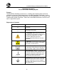
6510 Water Handling System Operating Instruction Manual Safety Information To avoid electrical shock, always: 1. Use a properly grounded electrical outlet of correct voltage and current handling capability. 2. Ensure that the equipment is connected to electrical service according to local national electrical codes. Failure to properly connect may create a fire or shock hazard. 3. For continued protection against possible hazard, replace fuses with same type and rating of fuse. 4.
6510 Water Handling System Operating Instruction Manual Description The system consists of a 20 liter, temperature controlled, tank with a built in circulating pump, an attached glass delivery pipet and provision for continuous filtration of all water in the system. This is a closed circuit system in which water is re-used continuously.
6510 Water Handling System Operating Instruction Manual Installation Install the 6510 System near the calorimeter so that the water connections are kept short. The water system can be installed in any convenient location however care should be taken that heat from the compressor on the left side of the Water Handling System not reach the calorimeter. Additionally, air must be allowed to move freely around the cooling fan on the back of the 6510 System.
510 Water Handling System Operating Instruction Manual Tubing Connections Water connections are not required for the 6100 Calorimeter. The two external water connections are made using the ¼” Nylon tubing, P/N HJ0025TB035, furnished with the system. For each connection, cut the end of the tube squarely with a knife or tubing cutter. The cooling water connections at the rear of the calorimeter use compression fittings.
6510 Water Handling System Operating Instruction Manual Preventative Maintenance All power should be disconnected when cleaning or servicing the instrument. The following preventative maintenance for the 6510 Water Handling System is recommended: Monitor the amount of water in the water tank and add water as required to maintain the water level in the reservoir. Clean the grill on the heat sink at the rear of the Water Handler monthly.
6510 Water Handling System Operating Instruction Manual Parts List Part No. Description 108C 110C 139E20 139E23 149C 172HW2 1795E 1850E Spout, Polyethylene 3” Tubing, Black Latex 3” Fuse 3AG Slo-Blo 250VAC 4.
6510 Water Handling System Operating Instruction Manual Figure 1 -9-
6510 Water Handling System Operating Instruction Manual Figure 2 - 10 -
6510 Water Handling System Operating Instruction Manual Figure 3A - 11 -
6510 Water Handling System Operating Instruction Manual Figure 3B - 12 -
6510 Water Handling System Operating Instruction Manual Figure 4A - 13 -
6510 Water Handling System Operating Instruction Manual Figure 4B WARNING: For continued protection against possible hazard, replace fuses with same type and rating of fuse.
6510 Water Handling System Operating Instruction Manual Figure 5 - 15 -
PARR INSTRUMENT COMPANY 211 Fifty-Third Street Moline, Illinois 61265 USA 309/762-7716 800/872-7720 Fax 309/762-9453 http://www.parrinst.com E-Mail: parr@parrinst.