
Instruction Manual

Parr Instrument Company www.parrinst.com
1” NPS Bottom Drain Valve Model A177VB2
Operating & Maintenance Instructions
661M
Description
The Parr Instrument Company A177VB2 Bottom
Drain Valve is a rising stem, process sampling
valve. In the closed position, the stem of the valve
is flush with the inside bottom of the vessel so that
there is minimal dead space between the bottom
of the vessel and the shut off point of the valve.
In the fully open position, the stem is retracted to
open a clear passage from the vessel. When the
valve is re-closed, any material in this passage will
be pushed back into the reactor by the rising stem.
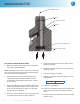
Installation and Operation
This valve is designed to be installed in the bot-
tom of Parr cylinders that are machined specifical-
ly for installation with minimal dead space. Nickel
based high temperature thread lubricant should
be applied to the valve body threads and then
installed turning clockwise into the cylinder. The
valve should be tightened sufficiently to seal on
the gasket which will bring the stem of the valve
approximately even with the inside bottom of the
cylinder.
The valve is opened by turning the shaft screw
counterclockwise. Opening the valve will progres-
sively increase the passage for product flow until
the valve is at the fully open position.
The valve is closed by turning the shaft screw
clockwise until the plunger contacts and com-
presses seal 1.
Typical torque values on the valve shaft screw
required to seal the valves are as follows:
A177VB2 25 – 30 ft/lbs
Caution!
If abrasive particles are run through
the valve, it is necessary to flush the
valve after use.
Significantly more torque should not be required
to seal the valve. If the valve is leaking, it is a good
indication that the seal may be worn, has been
damaged, or abrasive particles are interfering. The
valve should be disassembled, inspected, cleaned
as required, and seals replaced.
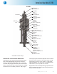
Disassembly of the Bottom Drain Valve
1. Retract the plunger to the fully open position
by turning the shaft screw counterclockwise.
2. Remove the (3) 5/16 flat countersunk socket
head screws from the screw shaft retainer us-
ing the 3/16” socket screw key furnished with
the BDV.
3. Loosen the (3) 5/16 socket head cap screws
that compress seal 2 with the retainer using
the 1/4” socket screw key furnished with the
BDV.
4. Pull the screw shaft retainer and plunger as-
sembly out of the valve body.
5. Remove the (3) standoffs.
6. Remove the (3) 5/16 socket head cap screws
and remove the retainer.
7. Using a solid object, press out the sleeve and
both seal 2. (See figure A-A)
8. Using a pick, remove seal 1 from the valve
body.