667M 5000 Multiple Reactor System Operating Instruction Manual For Models Produced After July 2013
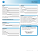
Table of Contents PREFACE 2 PARTS LIST 8 Scope 2 Vessel Parts 8 Related Instructions 2 Gasket and Seals 8 Intended Usage 2 Cables 8 Safety Information 2 Pressure Transducers 9 General Specifications 2 Gas Hose Assemblies 9 Explanation of Symbols 3 Rupture Discs 9 Environmental Conditions 3 Manifold Parts 9 Unpack Carefully 3 Provisions for Lifting and Carrying 3 Cleaning & Maintenance 3 User’s Responsibility 4 PRESSURE AND TEMPE
Table of Contents PREFACE 2. Ensure that the equipment is connected to electrical service according to local national electrical codes. Failure to properly connect may create a fire or shock hazard. Scope These instructions describe the installation, operation, and maintenance of the Parr Series 5000 Multiple Reactor System. They cover the basic steps to be followed for installing this system and describe the function of all standard components.
Multiple Reactor System Explanation of Symbols I On position, half power heater switch O Off Position ~ Alternating Current (AC) This CAUTION symbol may be present on the Product Instrumentation and literature. If present on the product, the user must consult the appropriate part of the accompanying product literature for more information. This CAUTION symbol indicates that the surface may be hot. Protective Earth (PE) terminal.
Multiple Reactor System User’s Responsibility All Parr Reactors and Pressure Vessels are designed and manufactured with great care to assure safe operation when used within their prescribed temperature and pressure limits. But…the basic responsibility for safety when using this equipment rests entirely with the user; who must: 1. Select a reactor or pressure vessel that has the capability, pressure rating, corrosion resistance, and design features that are suitable for its intended use.
Multiple Reactor System PRESSURE AND TEMPERATURE LIMITS Working pressures up to 3000 psi (207 bar) maximum are permissible in these reactors when constructed of Type 316 Stainless Steel. Contact Parr Customer Service if your vessel is not constructed of T316 Stainless Steel and you are unsure of the pressure and temperature limit. No attempt should be made to increase these limits by making alterations or by substituting components which are not recommended by Parr Instrument Company.
Multiple Reactor System INSTALLATION MAINTENANCE General Setup Guidelines Cleaning The Series 5000 Multiple Reactor System requires at least 10 square feet of work space on a sturdy bench or table in a well ventilated area with convenient access to an electric outlet. If the tabletop is not heat resistant it would be ideal to provide an insulated pad on which to set the vessels when hot. The chassis, manifold, and valves and fittings may be cleaned with a damp cloth.
Multiple Reactor System Periodic Pressure Tests Technical Support Each cylinder used in a Parr stirred reactor is tested under hydrostatic pressure to the higher of 1.43 times the rated working pressure at room temperature or 1.30 times the rated working pressure corrected for temperature before it is released from the factory. Micrometer caliper measurements are taken during this test to check the deflection of the walls under pressure.
Multiple Reactor System PARTS LIST Please see Diagrams section for additional parts. Vessel Parts Part No. A129VB Description Needle valve, 1/4"NPT x 1/4"T A147VB Needle valve, 1/4"NPT x 1/4"NPT 2898HC2 Adapter for head mounted vessels 3697HC* Thermowell, 5/16-24 THD, 5050/5051 FG , T316 3697HC2* Thermowell, 5/16-24 THD, 5050/5051 OR, T316 A1742E Gasket and Seals Part No.
Multiple Reactor System Pressure Transducers Rupture Discs Part No. Description Part No.
Multiple Reactor System DIAGRAMS Diagram 1: Layout diagram of 5000 Multiple Reactor System Diagram 2: 5050/5051 Vessel body diagram, PTFE seal and O-ring seal Diagram 3: 5050 Vessel, head mounted valves, manual inlet Diagram 4: 5050 Vessel, head mounted valves, check valve inlet Diagram 5: Manifold panel for head mounted valves Diagram 6: Manifold panel for remote mounted valves Diagram 7: Base assembly with heater and stirring assembly, 115V Diagram 8: Base assembly with heaters and stirring assembly, 230V
Multiple Reactor System Diagram 2: 5050/5051 Vessel Body Diagram, PTFE Eeal and O-ring Seal 1/4 NPT REF 1/4 NPT REF (6) 1932HC3DE COMPRESSION BOLTS REF 2891HC3 HEAD 2.50 A2888HC SCREW CAP W/BOLTS 2886HC COMPRESSION RING 2889HC SCREW CAP 2895HCHA FLAT GASKET 3698HC GASKET 2887HC** O-RING 3698HC GASKET 4.36 4.47 3697HC THERMOWELL (SEE NOTE) 2.69 2.50 3697HC2 THERMOWELL (SEE NOTE) 2.47 2920HC GLASS LINER (OPTIONAL) 2890HC CYLINDER 1.50 1.88 2.
Multiple Reactor System Diagram 3: 5050 Vessel, Head Mounted Valves, Manual Inlet A1906EP_ SERIES PRESSURE TRANSDUCER 154VB 45° ELBOW A129VB NEEDLE VALVE 1/4NPTM-1/4T 433HC4 OUTLET 1/4 NPTM 527HC ORIFICE RING 526HC_ OR 581HC_ SERIES RUPTURE DISC 49HC2* ORIFICE CONE 1394HC8 TRANSDUCER BODY 2867HC QUICK CONN ADAPTER 633HC3 SAFETY BODY 2683HC SLEEVE (2) 827HC O-RING (2) 2714HC HOSE CONN 825HC SNAP RING NOTES: 1) *-DENOTES SPECIAL MATERIAL 2) A2888HC SCREW CAP W/BOLTS 2886HC COMPRESSION RING AND 2890HC*
Multiple Reactor System Diagram 5: Manifold Panel for Head Mounted Valves * Note: Tubing length in inches. www.parrinst.
Multiple Reactor System Diagram 6: Manifold Panel for Remote Mounted Valves 3X A130VB2 ANGLE VALVE (REF) 6X A2864HC2 PTFE LINED QUICK DISCONNECT HOSE ASSEMBLY OR 6X A2864HC3 FLEXIBLE METAL QUICK DISCONNECT HOSE ASSEMBLY 6X 501VB SUPPORT, VIBRATION (REF) 6X 2868HC2 POST, QUICK DISCONNECT 6X TN2520HL 1/4-20 HEX KEPS NUT 12X SB1932BT06 10-32 X 3/8 BHSCS 12X TW19NL #10 INT TOOTH LOCK WASHER 6X 3014HC PLUG, HOLE 1/2 PLATED TO VESSEL #1 TO VESSEL #2 6X SB1932BT06 10-32 X 3/8 BHSCS 6X TN1932HL 10-32 HEX KEPS
Multiple Reactor System Diagram 6: Manifold Panel For Remote Mounted Valves (Continued) 6X A2864HC2 PTFE LINED HOSE ASSY (REF) OR 6X A2864HC3 FLEXIBLE METAL HOSE ASSY (REF) 6X A541VB SERIES RELIEF VALVE, 1/8 NPTM (OPTIONAL) 6X 2868HC2 POST, QUICK DISCONNECT (REF) 6X TN2520HL 1/4-20 HEX KEPS NUT (REF) 6X A1906EP__ SERIES PRESSURE TRANSDUCER 6X 179VBAD STREET TEE (OPTIONAL) 6X A525VB VALVE, STRAIGHT 1/8 NPTM X 1/8T 6X 552VBAD FEMALE ADAPTER, 1/4T X 1/8 NPTF 6X 605VBAD MALE ELBOW, 45 DEG, 1/4T X 1/8 NPTM
Multiple Reactor System Diagram 7: Base Stirrer Assembly, 115V 16 Parr Instrument Company
Multiple Reactor System Diagram 8: Base Stirrer Assembly, 230V www.parrinst.
667M R01 11/24/14