BBLAB017A0 English / Espanol ñ / Francais ç www.parrotuncle.
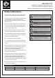
BBLAB017A0 Installation & Operating Instructions for the Parrot Uncle Owner's Installation, Manual WARNING: SHUT POWER OFF AT FUSE OR CIRCUIT BREAKER Safety Information 1. To reduce the risk of electric shock, the electricity has been turned off at the circuit breaker or fuse box before begin. 2. All wiring must be in accordance with the National Electrical Code NASI/NFPA70-1999 and local electrical codes. Electrical installation should be performed by a qualified licensed electrician. 3.
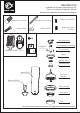
BBLAB017A0 Installation & Operating Instructions for the Parrot Uncle Owner's Installation, Manual WARNING: SHUT POWER OFF AT FUSE OR CIRCUIT BREAKER Plastic wire nut (4PCS) Mounting screws (2PCS) Screws (2PCS) Washer (2PCS) Blade screw (16PCS) Blade arm screws (11PCS) Mounting bracet Hanging Pin REMOTE CONTROL ( 1PC ) x6 4.
BBLAB017A0 Installation & Operating Instructions for the Parrot Uncle Owner's Installation, Manual WARNING: SHUT POWER OFF AT FUSE OR CIRCUIT BREAKER 1 Securely attach the hanger bracket to the outlet box using the screws and washers provided in the hardware bag. 2 Loosen the two coupling screws preassembled in the coupling , but do not remove them. Remove the locking pin and hanging pin from the downrod assembly. Retain for later use.
BBLAB017A0 Installation & Operating Instructions for the Parrot Uncle Owner's Installation, Manual WARNING: SHUT POWER OFF AT FUSE OR CIRCUIT BREAKER 4 5 Slide downrod into the coupling on top of the motor. Install the hanging pin by aligning the holes in the coupling with holes in the downrod. Secure hanging pin with locking pin. Securely tighten the two previously loosened set screws. Cut off excess lead wire approximately 6 to 9 inches above top of the downrod.
BBLAB017A0 Installation & Operating Instructions for the Parrot Uncle Owner's Installation, Manual WARNING: SHUT POWER OFF AT FUSE OR CIRCUIT BREAKER 6 Outlet box GREEN WHITE (N) BLACK (L) WHITE (AC IN N) GREEN GREEN BLACK (AC IN L) BLUE (FOR LIGHT) BLUE (FOR LIGHT) WHITE (TO MOTOR N) WHITE (FOR MOTOR) BLACK (TO MOTOR L) BLACK (FOR MOTOR) Slide the receiver into the open Loosen the screws without fully removing it.
BBLAB017A0 Installation & Operating Instructions for the Parrot Uncle Owner's Installation, Manual WARNING: SHUT POWER OFF AT FUSE OR CIRCUIT BREAKER 7 Securely attach and tighten the canopy cover over the screws in the mounting bracket utilizing the key slot twist-lock feature. Note: Adjust the canopy screws as necessary until the canopy and canopy cover are sung. 8 9 Position a blade arm under blade. Secure with three blade screws. Do not tighten blade screws until all three have been inserted.
BBLAB017A0 Installation & Operating Instructions for the Parrot Uncle Owner's Installation, Manual WARNING: SHUT POWER OFF AT FUSE OR CIRCUIT BREAKER 10 11 12 Remove one of the three screws in the support bracket at the bottom of the motor assembly and retain the screw for later and slightly loosen the remaining two screws. Assemble the switch housing to the support bracket using the two key slots. Replace the previously removed screw and securely tighten all three screws.
BBLAB017A0 Installation & Operating Instructions for the Parrot Uncle Owner's Installation, Manual WARNING: SHUT POWER OFF AT FUSE OR CIRCUIT BREAKER 13 Whole structure OPERATING YOUR FAN Turn on the power and check the operation of the fan. Fan Speed: “ ”Turn on the fan and turn speed up. “ ”Turn on the fan and turn speed down. The appropriate speed settings for warm or cool weather depends on factors such as the room size, ceiling height, and number of fans.
BBLAB017A0 Installation & Operating Instructions for the Parrot Uncle Owner's Installation, Manual WARNING: SHUT POWER OFF AT FUSE OR CIRCUIT BREAKER
BBLAB017A0 Installation & Operating Instructions for the Parrot Uncle Owner's Installation, Manual WARNING: SHUT POWER OFF AT FUSE OR CIRCUIT BREAKER WIRING SCHEMATIC DIAGRAM FOR RECEIVER Light live-wire To Motor wire To Motor wire Black wire Power supply live-wire Blue White Black White wire Power supply neutral-wire Antenna wire POWER PARAMETER LIST Voltage 120 V Fan (max.) 60W Lamp (max.
BBLAB017A0 Installation & Operating Instructions for the Parrot Uncle Owner's Installation, Manual WARNING: SHUT POWER OFF AT FUSE OR CIRCUIT BREAKER SIZE OF PRODUCT 2.2" 4.7" 10.9" 13.5" 1.5" 26.
BBLAB017A0 Installation & Operating Instructions for the Parrot Uncle Owner's Installation, Manual WARNING: SHUT POWER OFF AT FUSE OR CIRCUIT BREAKER TRO UB L ESH OOTIN G GU ID E 1.FAN / REMOTE IS NOT WORKING Ensure the remote is within the 20 foot range of the receiver To reset the remote control: 1) Turn off power to fan using the wall switch or circuit breaker. 2) Remove batteries from remote. 3) Wait 10 seconds.
BBLAB017A0 Installation & Operating Instructions for the Parrot Uncle Owner's Installation, Manual WARNING: SHUT POWER OFF AT FUSE OR CIRCUIT BREAKER AFTER INSTALLATION Wobble The fan blades have been adjusted in the factory to minimize any wobble Note: ceiling fans tend to move during operation due to the fact that they are mounted on a rubber grommet. If the fan was mounted rigidly to the ceiling, It would cause excess vibration.
120Vac 60W 18W
x6
120Vac 60W 18W
x6