PAR Drive-Thru System G5: G5 Basestation Model G5B1, G5 Headsets and XT-1 Headsets Improving communications that drive business.
Table of Contents 1. Overview ................................................................................................ 3 A. B. Safety Information .................................................................................................. 3 Other Conventions .................................................................................................. 5 2. Installation ................................................................................................. 7 A.
A. B. C. Headset Indicator Lights ......................................................................................... 49 General Troubleshooting ........................................................................................ 50 Battery and Battery Charger Troubleshooting .............................................................53 5. Appendix: Basestation Specifications ........................................................ 55 A. B. C. D. E. Physical ..................................
1. Overview A. Safety Information Safety Rules Read, understand, and follow all safety information contained in these instructions prior to installation & operation of G5 Basestation Model G5B1, XT-1 Headsets and the PAR Drive Thru Headset model G5H1. Failure to follow all instructions listed could result in electrical shock, fire and/or other personal injury. Retain these instructions for future reference.
WARNING To reduce the risks associated with fire, explosion & property damage: • Immediately discontinue use of the battery if, at any time, the battery feels hot, changes color or shape, emits an unusual smell, or appears abnormal or damaged in any other way. • Do not open, disassemble, pierce, crack, crush, incinerate, or expose to heat above 55 °C/130 °F. Keep batteries away from children. • Do not store or carry batteries with metal objects. Store batteries in cool, dry, clean places.
B. Other Conventions FCC and Industry Canada Information IMPORTANT NOTE FCC RF Exposure Statement: XT-1 Headset and the PAR Drive Thru Headset G5 comply with FCC RF radiation exposure limits set forth for an uncontrolled environment when operating based on time-averaged output power with duty cycle not to exceed 7.63% with a separation distance of 25mm. The wireless system must not be co-located or operating in conjunction with any other antenna or transmitter.
FCC and IC Identifiers: XT-1 Headset: FCC ID: DGFBCSDXT1H IC ID: 458A-BCSDXT1H G5 Basestation Model G5B1: FCC ID: DGFBCSDG5B1 IC ID: 458A-BCSDG5B1 PAR Drive-Thru Headset G5: FCC ID: DGFBCSDG5H1 IC ID: 458A-BCSDG5H1 IMPORTANT NOTE Modifications to this device shall not be made without the written consent of PAR Company. Unauthorized modifications may void the authority granted under Federal Communication Rules and Industry Canada Rules permitting the operation of this device.
2. Installation A. Overview of Installation Installation involves the following main steps: 1. Design the installation 2. Install the battery charger and begin charging the batteries. 3. Install the order point speaker and microphone assemblies. 4. Install the base station(s). 5. Install the vehicle detector loop(s). 6. Wire Greeter Alert trigger inputs 7. Power up the basestation 8. Configure the System and Greeter B.
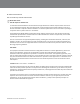
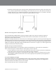
• A Single Drive-Thru (see Figure 1) is the most common configuration. It is comprised of one lane of traffic with one order point, and one or two drive-thru windows for payment and pick up. Figure 1. • A Tandem Drive-Thru (see Figure 2) is comprised of a single lane of traffic with two order points (one in front of the other) and one or two drive-thru windows for payment and pick up. Figure 2.
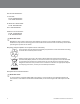
• A Dual Drive-Thru (see Figure 4) is comprised of two completely separate drive-thru systems, each with its own lane, usually on opposite sides of the building, its own order point, and one or two drive-thru windows for payment and pick up. The simplest dual drive-thru is two single drive-thrus, but it is possible to have dual tandem, dual side-by-side, or even a combination of different drive-thru types. Figure 4.
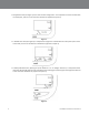
PAR Drive-thru Headset Battery Charger, G5 12-Slot The battery charger uses the same power adapter as the basestation. Perform the following steps to install and use the 12-slot battery charger. • • • • • • Figure 5. • Select a placement location, either: A flat, dry surface such as a desktop or shelf. An easy-to-reach wall. The power outlet must be near the equipment and be accessible, and cord placed where it cannot be pinched or bent.
• When charging is complete, the batteries are ready for use. Figure 6. IMPORTANT NOTE Power plugs are available on both sides of the stand-alone Battery Charger, G5, 12-slot to allow a connection to one additional Battery Charger, G5, 12-slot or a Headset Charging Station, G5 in serial using a patch cable. You may also use the power plug on the last charger in the interconnected chain to supply power to the basestation. IMPORTANT NOTE Both types of battery chargers can be mounted on the wall.
XT-1 6-Slot or 3-Slot Battery Charger Perform the following steps to install and use the 6-slot or 3-slot battery charger (see Figure 7). Figure 7. • Select a placement location: • A flat, dry surface such as a desktop or shelf. • An easy-to-reach wall location if you have the optional wall-mount bracket. • The power cord should be in place where it cannot be pinched or bent. • Install the wall-mount bracket on the wall, if applicable. • Place the charger on the wall-mount bracket or surface.
F. Install the Vehicle Detector(s) Follow the instructions provided with the vehicle detectors for installing the detector loop(s), speakers, and microphones. For information on wiring and configuring the vehicle detector(s) to the basestation see see “Basestation to Component Wiring” on page 20. For information on installing the vehicle detector circuit boards in the basestation, see “Installing Accessory Boards in the Basestation” on page 23. G.
Assembling the Control Pod and Carrier Follow the procedure below to assemble the Control Pod and Carrier to form a fully functional headset: 1. On the opposite side of the Headset Carrier, ensure that the Control Pod Locking Mechanism is in the unlocked position by sliding it all the way to the left. A small flat head screwdriver or other similar tool can be used to slide the locking mechanism if needed. See Figure 9 below. 2.
Figure 11. H. Install the Basestation Choose a Location Generally, the base station should be located centrally, and close to the order takers. However there are several important guidelines that must be followed to reduce the risk of problems. Follow the guidelines to ensure that the basestation(s) can communicate with headsets in any foreseeable location: • • • • • • Do not assume that the location of an old basestation is suitable for a new basestation. The LCD screen should be approximately 5 ft (1.
Removing and Replacing the Cover To remove the basestation cover: • Disconnect power from the basestation. • Loosen the two screws located at the bottom of the cover. • Lift the cover upward and away. The display and keypad remain with the base, not with the cover. To replace the basestation cover: • Verify there are no obstructions (tools, etc.) in the way of the cover being closed. • Align the top edge of the cover with the base.
™ Controltac™ Graphic The steps below assume that all of the communication cabling has been prepared and is available at the basestation. If not, see “Basestation to Component Wiring” on page 20. • Follow local best practices and any applicable regulations to route the cables into the basestation cabinet’s top, sides, or back (through the wall) as neatly as possible. Do not route power supply wiring with communication wiring in the same conduit. • Attach all cables to their appropriate terminals.
Table A. GENERAL PURPOSE INPUT / OUTPUTs (GPIOs) 16 configurable logical Inputs and Outputs. All Inputs and Outputs are Active Low and are factory set to the following signals. You can reassign any of these GPIOs to output or take as input a different signal. The GPIOs 15 and 16 are logically mapped to the 1_GRT_CNL and 2_GRT_CNL of Lane1 and Lane2 connectors, respectively. You will have to use the GND0 or GND1 from the GPIO terminal block.
Terminal Label Definition and Connection Information 1_SPKR_OUT- Negative phase order point speaker for Lane 1 1_GRT_CNL (GPIO15) Active low talk. Must use one of the GND0 or GND1 from GPIO terminal block.
J. Basestation to Component Wiring Good Wiring Practices To reduce interference and improve signal quality, use the following practices for all communication wiring: • • • • • • Keep shielding on the cable as close to the terminal as possible. Do not untwist pairs more than necessary. Do not allow cable strands to fray. Do not tin cable leads with solder. Fold un-insulated wire over onto itself before inserting into a terminal. Make sure screw terminals are tight.
Figure 15. K. Auxiliary Detector Relays You can use the basestation’s vehicle detection circuits to operate an auxiliary relay for a number of convenient uses (typically an external greeter or timer module but could also be used to operate a vehicle approach chime or other device that is independent of the intercom system). Virtually any device that can be activated by opening or closing a switch can be linked to vehicle detection.
Short Circuit Example Figure 16 shows a simple DC circuit (a light and DC power supply) being operated by the auxiliary relay. To make the light turn on when a vehicle is detected on Lane1, terminals R1_COM and R1_NO (normally open) would be used. To make the light turn off when a vehicle is detected Lane1, terminals R1_COM and R1_NC (normally closed) would be used. Figure 16.
Vehicle Approach Monitor Configure any of the 16 GPIOs to be used as a vehicle approach monitor. The relay closure signal to these GPIOs can be supplied by an external vehicle detector connected to an induction loop, in the drive-thru, which monitors an approaching vehicle. A typical wiring is illustrated in Figure 17. Figure 17. IMPORTANT NOTE GPIO15 and GPIO16 are located in the Lane1 and Lane2 Order Point Connectors. L.
Vehicle Detectors There are two available installation slots at the bottom of the base-station for vehicle detector boards, one for each lane of drive-thru operation. Once installed, each detector board must be configured for sensitivity, delay, and pulse/ presence detection. • Sensitivity—there are four available sensitivity settings: low, medium low, medium high, and high. Setting a high sensitivity increases vehicle detection but also increases the likelihood of false detection (e.g.
• Adjust the sensitivity of vehicle detection by manipulating the top two dip switches. • Enable or disable a two second detection delay by manipulating the third switch • Choose presence or pulse detection by manipulating the fourth switch. Figure 20. Vehicle Detector LED There are two small LEDs on the vehicle detector that can be in one of three states when powered and operating: • Steady green—indicates that power is applied and no vehicle is currently detected. • Flashing green, single flash every 1.
Greeter Alert Trigger Inputs The Greeter functionality is built into the G5 Basestation Model G5B1. In addition to playing back a Greet message to the customer at the Order Point and/or playing a Reminder message at a scheduled time of day, the user can also program the system to playback an Alert message whenever an external event occurs, such as Opening the Back Door or Opening the Refrigerator.
Run Mode Menu When the system is powered up and functioning normally, the Run mode menu appears on the display. Figure 22 shows the Run mode menu. Figure 22. Navigating in the Basestation in Run Mode To navigate the base station in Run mode you only need to use Enter, Mode, and the directional arrow buttons. The remaining buttons function only in manager or installer configuration modes.
3. Configuration A. Enter Configuration Mode Configuration mode is a passcode-protected area that contains most of the configuration options for the basestation system. Using the access provided for users it is possible to set up all of the functionality of the system. To enter the configuration mode: • • • • From the Run mode menu. Enter your user passcode. Press Mode. The display will show the user name and ID number (e.g., User1 ID = 1). Press Mode again.
Interpreting Display Information Depending upon what you are doing, or what you can do, text on the display screen is handled according to the following conventions: Static or Informational Static, informational, or noneditable text has no markings on it. Editable items that are not currently-selected appear inside of outwardly-pointing pointers. >Editable, Selected< Editable items that are currently selected appear inside of inwardly-pointing pointers.
C. Finding the MAC Address of the G5 Basestation To find the MAC address of the G5 Basestation. • Enter the configuration mode, see “Enter Configuration Mode” on page 28, and choose 1 System Menu. • Select 16 Network Setup. • Note the 6 pairs of alpha-numeric characters (enclosed in square brackets), against the MAC Address field. Note that your G5 Basestation may contain a different set of characters than the one illustrated below: Figure 24. D.
E. Logging into the Basestation with a PC Once the basestation is connected and configured you can log into it from any other computer on the network and operate the station as you would from the local interface. To log into the basestation: 1. Using a web browser, type in the IP address of the base station in the browser’s Address bar, then press Enter. 2. Type in your user name and password, then press Enter. a. The default user name is “User1”; the default password is “1234”. F.
G. Menu Options for Lane1 and Lane2 There are very few menu options that are available on Lane1 settings and not on Lane2; and vice versa. The table below provides a high level view of the menu structure for Lanes 1 and 2.
Menu Available on Lane1 Available on Lane2 - PAGE Messages Can Cross Lanes? Yes No - Order Point TALK With No Vehicle Yes No - “Pull Ahead” Prompt (Tandem ONLY) No Yes - Vehicle Detector #1 Type Yes No - Vehicle Detector #2 Type No Yes - Vehicle Detector #1 Minimum Yes No - Vehicle Detector #2 Minimum No Yes Yes No - External Audio-In Routing Mode Yes No - Ext.
Outbound Talk Volume Changing the outbound talk volume affects the volume of the speaker at the customer order point. IMPORTANT NOTE To avoid feedback, set the outbound talk volume as low as possible. To change the outbound talk volume: • Enter the configuration mode, see “Enter Configuration Mode” on page 28, and choose 1 System Menu. • Select a new value for 01 Drivethru Volume > Outbound Talk Volume. The range is 0 (silent) to 20 (max).
IMPORTANT NOTE To avoid feedback and echo, set the outbound talk volume as low as possible. To change the outbound talk monitoring settings: • Enter the configuration mode, see “Enter Configuration Mode” on page 28, and choose 1 System Menu. • Select 02 Monitor Volume. • To enable or disable the monitor playing the outbound talk, change the value for Outbound Talk: Enable to ON or OFF. • To change the volume level, select a new value for Outbound Talk: Volume. The range is 0 (silent) to 20 (maximum).
• To change the volume level, select a new value for PAGE Messages: Volume. The range is 0 (silent) to 20 (maximum). Greeter Messages Changing the greeter message volume affects how loudly the monitor plays the greeter messages. You can also disable the monitor playing the greeter messages. To change the greeter message volume monitoring settings: • Enter the configuration mode, see “Enter Configuration Mode” on page 28, and choose 1 System Menu. • Select 02 Monitor Volume.
Registering Headsets Each headset must be registered to a basestation before it can be used. XT-1 headsets have a single serial number. This number is imprinted on the headset. G5 headsets have 2 serial numbers - one for the G5 Control Pod and the other for the G5 Carrier. The G5 Control Pod serial number is the primary tracking number for the G5 headset and this is the serial number that gets registered on the basestation.
• Read the serial number off this field. Figure 26. IMPORTANT NOTE This field will only display the last 7 digits of the Headset’s (or G5 Control Pod’s) serial number. List All Headsets To see a list of the registered headsets: • Enter the base station configuration mode, see “Enter Configuration Mode” on page 28, and choose 1 System Menu. • Select 04 Registration > 3 List All Headsets. Resetting Inactive Days For any headset, you can manually reset its number of inactive days to zero.
Identifying Headset Serial Number To identify the last 7 digits of a XT-1 headset or G5 Control Pod) registered to this basestation: • Enter the base station configuration mode, see “Enter Configuration Mode” on page 28, and choose 1 System Menu. • Navigate to 08 Headset Setup. • Pay attention to the Serial Number displayed in the Headset Selection Field to the right of Currently Editing Headset. • Conduct a PAGE with the operational XT-1 or G5 Headset on hand.
Text and Audio Prompts Language You can choose between English, Spanish, German, and French language for all text and audio prompts, which is essentially all of the factory prerecorded information coming from the base station and all of the printed text on the display. IMPORTANT NOTE Changing the text and audio prompt language will also change the language of the headset messages.
• Enter the base station configuration mode, see “Enter Configuration Mode” on page 28, and choose 1 System Menu. • Change the value for 07 Global Settings > ’’Store is Now Closed’’ Prompt? to Yes or No. Pull Ahead Prompt You can let customers know to pull ahead when they are at order point #2 in a tandem drive-thru when: • it is out-of-service. • no car is present at order point #1. Pick Up Cash Order Point #2 Order Point #1 Figure 27. This option is available on Lane2 settings only.
Order Takers and Page Messages in Cross Lane Mode In systems with two customer order points, in cross lane mode, you must specify the number of order takers you will be using to make sure that non-order takers can hear orders being taken on one or both lanes. Similarly, you must specify whether you want page messages to be heard by all headsets or only within each lane. Perform the following procedure to specify the number of order takers in cross lane mode.
• Gently vibrate and/or • Flash a Blue LED (at the tip of the mic boom) when a vehicle is detected at the Order Point. These options are, by default, set to YES. This option only applies to G5 headsets. If you currently have no G5 headsets and only XT-1 headsets, then enabling or disabling this option will not affect the normal functioning of the XT-1 headset.
Regular Site Schedule The regular site schedule is the opening and closing times for each day of the week and the times assigned as “Day” and “Night,” which determine when the day and night volume settings change. Perform the following procedure to set the regular site schedule: • Enter the base station configuration mode, see “Enter Configuration Mode” on page 28, and choose 1 System Menu. • Navigate to 10 Site Scheduling > Regular Site Schedule.
P. Digital IO Setup The Digital IO Setup allows you to configure the 16 logical General Purpose Input and Output ports. All Inputs and Outputs are Active Low. You can reassign any of these GPIO ports to either, provide a signal (OUT) or accept a signal (IN). You can assign what action the basestation needs to take upon receiving a signal (IN) on one of these ports.
• Identify the user number you want to change, then press the directional arrows as necessary to scroll to the desired passcode. • Enter a new four-digit passcode in place of the old passcode. • Press Enter to implement the change or press Mode to abandon the change and leave the passcode at its previous setting. R. Split and Cross Lane Mode In any dual lane installation (tandem, side-by-side, or dual drive thrus), the system can be configured to operate registered headsets in Split or Cross Lane Mode.
• Change the value for Save Installation Settings to Yes. Technical Service Message Perform the following procedure to customize the Service Screen message. • • • • Enter the configuration mode, see “Enter Configuration Mode” on page 28, and choose 1 System Menu. Select 14 Installer Setup. Change the value for Use Custom Tech Service Message? to Yes or No. If you chose Yes, enter the customer message.
• Press Enter. W. Check the Revision Levels Perform the following procedure to view the revision levels and serial numbers of your basestation: • Enter the configuration mode, see “Enter Configuration Mode” on page 28, and choose 1 System Menu. • Select 18 Revision Levels. X. Change the Microphone Preamp Gain The Mic Preamp Gain is the first stage of amplification from the microphone in the order point. In order to optimize the basestation to a specific site this level must be precisely set.
4. Troubleshooting A. Headset Indicator Lights The following table describes the operating modes of the headsets according to the indicator lights. Use it as a troubleshooting reference. Table B. G5 Battery Indicator Light Modes Indicator Mode Description Green LEDs The battery is out of the G5 battery Charger and the button has been pressed and held down. Each LED represents 25% charge. A fully charged battery would have all 4 LEDS lit Green.
Single Red Flash (changed from flashing green) Short red flash – Battery is inserted Headset is powering up from Hibernate Slightly longer red flash – Headset signs on to the base (as it transitions from flashing green to solid green) Alternating Flashing Green and Red Page Monitor Mode. Red -> (Red+Green) -> Red -> Green -> Red –> (Red+Green) –> Red –> Green Headset registered to four base stations. Perform the following procedure to clear the headset registration data: 1.
Problem Possible Cause Solution No vehicle alert tone in all headsets. No power to the external vehicle detector. Plug the vehicle detector into power outlet or replace the detector fuse. Vehicle detector is “locked up”. Remove power to vehicle detector for a few seconds to reset the detector. The base station alert tone volume is set too low. Adjust alert tone volume. This is normal when a pulse (air switch) type of vehicle detector is used. Press the Page switch to silence the menu microphone.
Problem Possible Cause Solution The “hands free” function does not work. The system is operating in half duplex mode. Hands Free is disabled in half duplex mode. Hands free order taking mode not selected. Select hands free order taking mode in the basestation. No vehicle alert tone in headset. Backup switch not completely pressed (i.e., one of the other two buttons is pressed). Press the other button into the correct location.
Figure 28. C. Battery and Battery Charger Troubleshooting Table E. XT-1 Battery and Battery Charger Problem Possible Cause Solution No lights come on when a battery is inserted into charger. Dirty contacts on battery or charger. Clean contacts on battery and charger. No power to charger. Make sure power transformer is plugged into charger and a “live” outlet. Defective battery. Try a known good battery. Defective charger. Call for authorized service. Short battery life.
Table F. G5 Battery Indicator Light Modes Indicator Mode Description Green LEDs The battery is out of the G5 battery Charger and the button has been pressed and held down. Each LED represents 25% charge. A fully charged battery would have all 4 LEDS lit Green.
6. Appendix: Basestation Specifications A. Physical Parameter Specification or Requirement Dimensions (l x w x d) 16 ¾ in. x 11½ in. x 2 in. (41.8 cm x 29 cm x 5 cm) B. Electrical Parameter Specification or Requirement Input Power 120 VAC, 50/60 Hz, 15A Standard 3-prong outlet required (station includes AC adapter) Radio Frequency 2401.92 MHz - 2479.68 MHz ISM Maximum Output Power (EIRP) 20 dBm Speaker Outputs 5W C.
7. Appendix: Induction Loop and Vehicle Detector Board Specifications A. Internal Vehicle Detector Board Specifications Parameter Specification or Requirement Size 2.5 in. x 3.0 in. (5.1 cm x 7.6 cm) Power Supply Type Supply from G5 Basestation G5B1 terminals Voltage 12 DC nominal Current 50 mA maximum Connector 3 wire plug in connector to G5 Basestation G5B1 B. Saw - In Loop Specifications Parameter Specification or Requirement PAR Detector Loop Sealant 2 each, 1 quart cartridges.
8. Appendix: G5 Charger Specifications A. Physical Parameter Specification or Requirement G5 Desk Charger G5 Wall Charger Dimensions (l x w x d) 6.4” x 5.6” x 2.0” (162mm x 143mm x 51mm) 19.5” x 3.2” x 2.7” (495mm x 81mm x 68mm) Weight (fully loaded) 1.3 lbs (0.6kg) 2.9 lbs (1.3kg) B.
9. Appendix: Best Practices This appendix provides best practices to help ensure successful configuration and operation of G5 Basestation Model G5B. A. PreAmp Setting Set the PreAmp gain setting according to the type of wiring you are using: • If you are using the provided PAR Microphone and the 20 AWG cable, set the PreAmp gain setting to 8. • If a 22 AWG cable is used, set the PreAmp gain setting to 9. B.
D. Dealing with Delay/Echo During the first ½ second of each order, there is a delay while the Order Taker starts to speak. If the Delay lasts more than a ½ second, follow the flowchart (Figure 29) below. You may also experience a delay if a vehicle at the order point moves while the order is taking place; this usually happens at the end of a call while the order taker tells the customer the total. Echo/Delay Cancellation Flowchart 59 Figure 29.
10. Appendix: PAR Acoustic Kit Installation Guide The PAR Acoustic Kit that is used for communication posts is suitable for new or retrofit installations and can readily be used with various housing designs. One kit contains enough material to accommodate a typical microphone and speaker system. It can be used for a microphone and speaker installed either in a single housing or in separate housings.
C. Installation Guidelines - Single Housing Microphone and speaker are contained within a single housing. Component installation is the same for both microphone and the speaker. The microphone and speaker must be separated from each other by foam. • Ensure that the inside of the housing is clean and dry. • Install the PAR Vibration Control Tape to the inside of the top and side walls of the housing (fig.4).
Additional illustrations of PAR speaker and microphone installation using the PAR Acoustic Kit and product instructions as a guideline for installation.
11.Appendix: Loop and Cable Condition Test Measure loop inductance/resistance for each order point, recommend replacement in comments section if needed. You must conduct two separate tests on the Inductance Loop to determine it’s condition: A. Lineal Conductor Resistance and Inductance This test measures the Resistance and the Inductance of the loop conductor or wire at the Basestation.
12. Appendix: Upgrading a Single Lane Basestation to a Dual Lane A 7-digit code is necessary in order to upgrade the software on the single lane G5 basestation to enable the dual lane capabilities. This 7-digit code is unique to each basestation and is based on the MAC IP Address.
13.
Warranty, Limited Remedy, and Disclaimer PAR warrants that its intercom products will be free from defects in material and manufacture for the period indicated in product literature from the date of shipment to purchaser by PAR or its authorized dealer. PAR MAKES NO OTHER EXPRESS OR IMPLIED WARRANTIES, INCLUDING ANY IMPLIED WARRANTY OF MERCHANTABILITY OR FITNESS FOR A PARTICULAR PURPOSE.