
Installation Manual

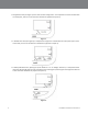
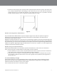
Table Of Contents
- A. Safety Information 3
- B. Other Conventions 5
- A. Overview of Installation 7
- B. Required Materials (Not Supplied) 7
- C. Design the Installation 7
- D. Install the Battery Charger 9
- E. Install the Order Point Speaker and Microphone Assemblies 12
- F. Install the Vehicle Detector(s) 13
- G. Assemble the PAR Drive Thru Headset G5. 13
- H. Install the Basestation 15
- I. Connect the Components 17
- J. Basestation to Component Wiring 20
- K. Auxiliary Detector Relays 21
- L. Installing Accessory Boards in the Basestation 23
- M. Power Up 26
- A. Enter Configuration Mode 28
- B. Navigating the Basestation Display 28
- C. Finding the MAC Address of the G5 Basestation 30
- D. Configuring with a Computer 30
- E. Logging into the Base Station with a PC 31
- F. Switching Between Lane1 and Lane2 31
- G. Menu Options for Lane1 and Lane2 32
- H. Change Basic Volume Settings 33
- I. Change Noise Reduction Level 39
- J. Set System Date and Time 39
- K. Change Global Settings 39
- L. Haptics “Vibration” Alerts and Blue LED Alerts on Headsets 42
- M. Order Taking Modes Setup 43
- N. Change Site Scheduling 43
- O. Change Site Information 44
- P. Digital IO Setup 45
- Q. Change Passcodes 45
- R. Split and Cross Lane Mode 46
- S. Installer Setup 46
- T. Factory Setup (Restore Factory Defaults) 47
- U. Create and Load Templates 47
- V. Reboot System 47
- W. Check the Revision Levels 48
- 1. Overview
- 2. Installation
- A. Overview of Installation
- B. Required Materials (Not Supplied)
- C. Design the Installation
- D. Install the Battery Charger
- E. Install the Order Point Speaker and Microphone Assemblies
- F. Install the Vehicle Detector(s)
- G. Assemble the PAR Drive Thru Headset G5H1
- H. Install the Basestation
- I. Connect the Components
- J. Basestation to Component Wiring
- K. Auxiliary Detector Relays
- L. Installing Accessory Boards in the Basestation
- M. Power Up
- 3. Configuration
- A. Enter Configuration Mode
- B. Navigating the Basestation Display
- C. Finding the MAC Address of the G5 Basestation
- D. Configuring with a Computer
- E. Logging into the Basestation with a PC
- F. Switching Between Lane1 and Lane2
- G. Menu Options for Lane1 and Lane2
- H. Change Basic Volume Settings
- Inbound Microphone Volume
- Outbound Talk Volume
- Vehicle Alert Volume
- Outbound Greeter Message Volume
- Change the Monitor Volume
- Inbound Listen
- Outbound Talk
- Vehicle Present
- Vehicle Approach
- Page Messages
- Greeter Messages
- Monitoring Audio Separately for the Two Lanes
- Change the Night Volume
- Registering Headsets
- Add Headsets
- Remove Headsets
- List All Headsets
- Resetting Inactive Days
- Checking Headset Software Revision
- Identifying Headset Serial Number
- I. Change Noise Reduction Level
- J. Set System Date and Time
- K. Change Global Settings
- L. Haptics “Vibration” Alerts and Blue LED Alerts on Headsets
- M. Order Taking Modes Setup
- O. Change Site Information
- P. Digital IO Setup
- Q. Change Passcodes
- R. Split and Cross Lane Mode
- S. Installer Setup
- T. Factory Setup (Restore Factory Defaults)
- U. Create and Load Templates
- V. Reboot System
- W. Check the Revision Levels
- X. Change the Microphone Preamp Gain
- Y. Installer Access
- 4. Troubleshooting
- 6. Appendix: Basestation Specifications
- 7. Appendix: Induction Loop and Vehicle Detector Board Specifications
- 8. Appendix: G5 Charger Specifications
- 9. Appendix: Best Practices
- 10. Appendix: PAR Acoustic Kit Installation Guide
- 11. Appendix: Loop and Cable Condition Test
- 12. Appendix: Upgrading a Single Lane Basestation to a Dual Lane
- 13. Index

Installation Instructions G5 Release A
7
2.
Installation
A.
Overview of Installation
Installation involves the following main steps:
1.
Design the installation
2.
Install the battery charger and begin charging the batteries.
3.
Install the order point speaker and microphone assemblies.
4.
Install the base station(s).
5.
Install the vehicle detector loop(s).
6.
Wire Greeter Alert trigger inputs
7.
Power up the basestation
8.
Configure the System and Greeter
B.
Required Materials (Not Supplied)
•
Standard or surface-mount conduit (metal or plastic) to enclose all system wiring.
•
Assortment of sheet metal screws and wall anchors.
•
Sufficient 18 to 20 AWG, (1.02 to 0.81mm diameter) shielded twisted pair audio cable, sufficient in length to
connect the speaker and microphone assembly from the order point to the base station.
•
Recommend basic tool kit - screw drivers, pliers, wire strippers, crimping tools, scissors, soldering iron, solder,
crimp caps, electrical tape, wire ties, etc.
IMPORTANT NOTE
The twisted pair of wires for the microphone connection must be shielded for proper operation. In duplex
systems, microphone and speaker cannot be in the same jacket unless specially designed for duplex such as
PAR
Cable part number 78-8117-4313-3.
•
Sufficient shielded twisted-pairs of audio cable to connect other components such as grill monitor speaker,
vehicle detection device, etc.
C.
Design the Installation
There are multiple ways to install the intercom system. Before you begin you must understand how many components
you will be installing and where they must be installed. Use the installation checklist (if available) and these instructions
to assist you in designing the system.
Determine the Drive-Thru Type(s)
Following is a brief description of each drive-thru type: