
Data Sheet

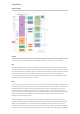
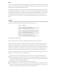
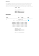
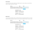
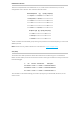
Table Of Contents
- Tracker SoM Datasheet (008)
- Functional description
- Interfaces
- Memory map
- Pins and connectors
- Technical specifications
- Mechanical specifications
- Certification
- Product Handling
- Default settings
- Ordering Information
- Revision history

Thereare10exposedGPIOlineslabeledA0-A7,TX,andRX.Thesemulti-functionpinscanbe
configuredforuseasGPIOorotherinterfaceslikeSPIandI2C.
SharedPeripherals Qty Input(I)/Output(O)
Digital 10(max) I/O
Analog(ADC) 8(max) I
UART 1 I/O
SPI 1 I/O
I2C 1 I/O
PWM
10(max)
1
O
PeripheralType Qty Input(I)/Output(O)
USB 1 I/O
NFCTag 1 O
CANBus 1 I/O
1
PWMisdividedintothreePWMgroups.Eachgroupmustsharethesamefrequency,butcanhave
differentperiods.
Note:AllGPIOareonlyratedat3.3VDCmax.CANbushasa highervoltagerating.
TheAssetTrackerSoMexposesthenRF52SWDinterfaceonthefollowingpins.TheEvaluation
Boardconnectsthesepinstothe2x5connectorusedontheArgonandBorontoeasilyconnectthe
ParticleDebugger.
# Pin Function ConnectedTo Description
22 SWDIO JTAG nRF52 nRF52MCUSWDIO
23 SWDCLK JTAG nRF52 nRF52MCUSWDCLK
24 SWO JTAG nRF52 nRF52MCUSWO
Thisinterfacecanbeusedtodebugyourcodeorreprogramyourbootloader,deviceOS,orthe
userfirmware.
PERIPHERALSANDGPIO
JTAG(SWD)