Instruction Manual and Experiment Guide 012-05024G ® *012-05024* 2.
2.2 m Classic Dynamics System T a b l e o f C o n t e n ts Introduction . . . . . . . . . . . . . . . . . . . . . . . . . . . . . . . . . . . . . . . . . . . . . . . . . . . . . . . . . . . 5 About the Equipment . . . . . . . . . . . . . . . . . . . . . . . . . . . . . . . . . . . . . . . . . . . . . . . . . . . . 6 Spare Parts . . . . . . . . . . . . . . . . . . . . . . . . . . . . . . . . . . . . . . . . . . . . . . . . . . . . . . . . . . . 9 About the Experiments. . . . . . . . . . . . . . . . . . . .
2.
Included Equipment Quantity Replacement Part Number 1. Plunger Cart 1 ME-9340 2. Collision Cart 1 ME-9454 3. 250 g Compact Cart Masses 2 ME-6755 4. 500 g Cart Mass 1 ME-6757 5. Adjustable End Stops 2 ME-8971 (2-pack) 6. 2.2 m Dynamics Track 1 ME-9779 7. Adjustable Feet 2 ME-8972 (2-pack) 8. Harmonic Springs 4 ME-9803 (3-pack) 9. Friction Block 1 ME-9807 10. Pivot Clamp 1 ME-9810 11. Super Pulley with Clamp 1 ME-9448A 12. Angle Indicator 1 ME-9495 13.
2.2 m Classic Dynamics System About the Equipment About the Equipment Track The 2.2 m aluminum track has two groves to guide the wheels of carts, a metric scale for measuring cart positions, and T-slots on both sides for attaching end stops, leveling feet and other accessories. Tip: The track is designed to support the weight of carts and related apparatus. Excess weight will warp it. When you store the track, ensure that no heavy object will be placed on top of it.
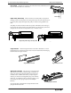
Model No. ME-9452 A b o u t th e E q u i p m e n t Adjustable Feet Attach the feet to the track as illustrated. Turn the feet screws to level the track then tighten the lock nuts to secure them. For maximum stability, position the feet about 1/4 of the track length from each end 1 2 4 3 1/4 1/4 Adjustable Feet 1: Slide tab into T-slot. 2: Tighten thumbscrew to secure feet set. 3: Turn feet screws to level track. 4: Tighten lock nuts to secure feet screws.
2.2 m Classic Dynamics System About the Equipment Pivot Clamp Attach the pivot clamp to the T-slot of the track (as illustrated) to elevate one end of the track on a vertical rod. T-slot Pivot Clamp Super Pulley with Clamp This low-friction, low-inertia pulley is designed for clamping onto the end of the track. Tie a string to the hole in the end of the cart an run it over the pulley. Adjust the height of the pulley to make the string parallel to the track.
Model No. ME-9452 Spare Parts Spare Parts You can order any of the major components of the system using the part numbers listed in the table on page 5. For an assortment of smaller parts, the following kits are available. IDS Spares Kit (ME-9823) and harmonic springs. This kit includes assorted thumbscrews, square nuts, Cart Launcher Springs Kit (ME-6847) This kit includes four compression springs and four release pins for the Spring Cart Launcher.
2.
Model No. ME-9452 Experiment 1: Conservation of Momentum in Explosions Experiment 1: Conservation of Momentum in Explosions Required Equipment from Dynamics System Track with Feet and End Stops Plunger Cart Collision Cart Cart Masses Other Required Equipment Suggested Model Number Mass set ME-9348 Purpose The purpose of this experiment is to demonstrate conservation of momentum with two carts pushing away from each other.
2.2 m Classic Dynamics System Experiment 1: Conservation of Momentum in Explosions Figure 1.1 2. For each of the cases in Table 1.1, place the two carts against each other with the plunger of one cart pushed completely in and latched in its maximum position (see Figure 1.1). 3. Tap the plunger release button with a short stick and watch the two carts move to the ends of the track. Experiment with different starting positions until the two carts reach the ends of the track at the same time.
Model No. ME-9452 Experiment 2: Conservation of Momentum in Collisions Experiment 2: Conservation of Momentum in Collisions Required Equipment from Dynamics System Track with Feet Plunger Cart Collision Cart Other Required Equipment Paper (for drawing diagrams) Purpose The purpose of this experiment is to qualitatively explore conservation of momentum for elastic and inelastic collisions.
2 . 2 m C la s s ic D y n a m i c s S y s t e m E x p e r i m e n t 2 : C o n s e r v a t i o n o f M o m e n t u m i n C o l l i s i o n s Case A2: Start the carts with one at each end of the track. Give each cart approximately the same velocity toward each other. Case A3: Start both carts at one end of the track. Give the first cart a slow velocity and the second cart a faster velocity so that the second cart catches the first cart. B.
Model No.
2 . 2 m C la s s ic D y n a m i c s S y s t e m Experiment 3: Simple Harmonic Oscillator 6. Tie a string to the end of the cart farther from the pulley. Wrap the string under the cart; then run it under one end stop and over the pulley as shown in Figure 3.1. Attach the mass hanger to the other end of the string. Adjust the pulley so that the string runs parallel to the track. 7. Let the mass hang freely and wait for the cart to come to rest.
Model No. ME-9452 3. Experiment 3: Simple Harmonic Oscillator Using the mass of the cart and the spring constant, calculate the theoretical period of the cart alone and with added mass. theoretical period of cart alone ________________ theoretical period of cart with added mass ________________ Experimental Period 1. Using the data in Table 3.2, calculate the average time for 5 oscillations with and without the 500 g mass in the cart. 2.
2.
Model No. ME-9452 Experiment 4: Oscillations on an Incline the pivot clamp and support stand to hold the track at this angle. Measure this angle and record it in Table 4.1. 5. Let the cart hang freely and come to rest. Record the equilibrium position in Table 4.1. 6. Add mass to the cart and record the new resting position. Repeat this for a total of 5 different masses, being careful not to over-stretch the spring. Table 4.
2.2 m Classic Dynamics System 2. Experiment 4: Oscillations on an Incline Calculate the period by dividing these average values by 3 and record the periods in Table 4.2. Table 4.2: Experimental Period Time for 3 Oscillations Angle Trial 1 Trial 2 Trial 3 Trial 4 Trial 5 Average Period Questions 20 1. Does the period vary as the angle is changed? 2. How do the experimental values compare with the theoretical values? 3. Does the equilibrium position change as the angle is changed? 4.
Model No. ME-9452 Experiment 5: Springs in Series and Parallel Experiment 5: Springs in Series and Parallel Required Equipment from Dynamics System Track with End Stops Cart Pivot Clamp Harmonic Springs (2) Other Required Equipment Suggested Model Number Base and support rod ME-9355 Stopwatch ME-1234 Mass balance SE-8723 Purpose In this experiment, you will measure and compare the periods of oscillation of a cart attached to various combinations of springs.
2.2 m Classic Dynamics System 4. 5. E x p e r i m e n t 5 : S p r i n g s i n S e r ie s a n d P a r a l l e l Incline the track by raising the end where the spring is attached. As the end of the track is raised the spring will stretch. Incline the track by raising the end of the track where the spring attached. As the end of the track is raised the spring will stretch. Keep the angle of inclination of the track small enough so the spring is not stretched more than about 50 cm.
Model No. ME-9452 Experiment 6: Launch Speed Experiment 6: Launch Speed Required Equipment from Dynamics System Track with Feet and End Stops Plunger Cart Pivot Clamp Cart Masses Purpose In this experiment, you will qualitatively demonstrate how the final speed of the plunger cart depends on its mass and the initial compression of the plunger spring. Procedure 1. Install the feet on the track and level it. 2. Install and end stop at each end of the track. 3.
2.2 m Classic Dynamics System Experiment 7: Newton’s Second Law Experiment 7: Newton’s Second Law Required Equipment from Dynamics System Track with Feet and End Stop Cart Super Pulley with Clamp 500 g Cart Mass Other Required Equipment Suggested Model Number Stopwatch ME-1234 Mass hanger and mass set ME-9348 Mass balance SE-8723 String (about 2 m) Purpose In this experiment, you will verify Newton’s Second Law, F = ma. Theory Figure 7.
Model No. ME-9452 Experiment 7: Newton’s Second Law 5. Pull the cart back until the mass hanger reaches the pulley. Record this initial release position in Table 7.1. This will be the release position for all the trials. Make a test run to determine how much mass is required on the mass hanger so that the cart takes about 2 seconds to complete the run. Because of reaction time, too short of a total time will cause too much error. However, if the cart moves too slowly, friction causes too much error.
2 . 2 m C la s s ic D y n a m i c s S y s t e m E x p e r im e n t 8 : A c c e l e r a t i o n D o w n a n I n c li n e Experiment 8: Acceleration Down an Incline Required Equipment from Dynamics System Track with End Stop Cart Pivot Clamp Other Required Equipment Suggested Model Number Base and support rod ME-9355 Stopwatch ME-1234 Graph paper Purpose In this experiment, you will investigate how the acceleration of a cart rolling down an inclined track depends on the angle of incline.
Model No. ME-9452 Experiment 8: Acceleration Down an Incline stopwatch. Repeat this measurement 10 times (with different people doing the timing). Record all the values in Table 8.1. 5. Lower the end of the track by 1 cm and repeat step 4. Use the same release position. 6. Repeat step 4 for a total of 7 angles, lowering the end of the track by 1 cm for each new angle. Table 8.
2 . 2 m C la s s ic D y n a m i c s S y s t e m 4. E x p e r im e n t 8 : A c c e l e r a t i o n D o w n a n I n c li n e Measure the hypotenuse of the triangle formed by the track and use this to calculate sin for each angle. Hypotenuse = __________ 5. Plot acceleration versus sin . Draw the best-fit straight line and calculate its slope. Calculate the percent difference between the slope and g = 9.8 m/s2. slope = ______________________ % difference = _______________ Questions 28 1.
Model No.
2.2 m Classic Dynamics System Experiment 9: Conservation of Energy Part I: Spring Constant Procedure 1. Fit the spring cart launcher onto the top of the cart (as illustrated). Tighten the thumbscrews to secure it. 2. Select one of the included springs. Slide it onto the launcher shaft with the flared end out. Turn the spring to secure the end in the spring retention hole as illustrated. 3. Tie the string to the release pin. Release pin Thumbscrews Flared end String 4.
Model No. ME-9452 Experiment 9: Conservation of Energy Part II: Spring Potential Energy and Kinetic Energy Procedure 1. Place a second end stop on the track about 8 cm behind the first end stop. 2. Elevate one end of the track by about 20 cm. 3. Hold the cart on the track with the launcher shaft through the hole in the first end stop, and with the spring just touching the end stop, but not compressed. Record this position of the cart as x 1. 4.
2 . 2 m C la s s ic D y n a m i c s S y s t e m T e c h n ic a l S u p p o r t Technical Support For assistance with any PASCO product, contact PASCO at: Address: PASCO scientific 10101 Foothills Blvd. Roseville, CA 95747-7100 Phone: 916-786-3800 (worldwide) 800-772-8700 (U.S.) Fax: (916) 786-7565 Web: www.pasco.com Email: support@pasco.com Limited Warranty For a description of the product warranty, see the PASCO catalog. Copyright The PASCO scientific 012-05024G 2.