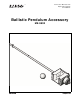
Instruction Manual with Experiment Guide 012-09842C ® Ballistic Pendulum Accessory ME-9892
Ballistic Pendulum Accessory Introduction . . . . . . . . . . . . . . . . . . . . . . . . . . . . . . . . . . . . . . . . . . . . . . . . . . . . . . . . . . . 4 Equipment Set-up . . . . . . . . . . . . . . . . . . . . . . . . . . . . . . . . . . . . . . . . . . . . . . . . . . . . . . 4 Assemble the Apparatus, 4 Load the Launcher, 5 Prepare the Sensor, 6 Test Fire, 6 Foam Insert Replacement . . . . . . . . . . . . . . . . . . . . . . . . . . . . . . . . . . . . . . . . . . . . . . .
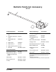
Ballistic Pendulum Accessory ME-9892 1 2 3 4 5 6 7 Included Equipment Part Number 1. Catcher and pendulum ME-9892 rod Optional Equipment Part Number Photogates (qty. 2)2 ME-9498A or similar Digital Adapter1, 2 PS-2159 Photogate Mounting Bracket2 ME-6821 Super Pulley with Clamp2 ME-9448B ME-8979 or similar 2. Pendulum attachment screw 613-076 3. Replaceable foam insert 648-09757 4. Ballast mass 648-06511 Hanging mass2 5.
Ballistic Pendulum Accessory Introduction Introduction Use the Ballistic Pendulum Accessory in combination with a Short Range Launcher and Rotary Motion Sensor (RMS) to measure the velocity of a steel ball and study rotational collisions. The launcher shoots the ball into the Ballistic Pendulum Accessory. The RMS measures the resulting angular displacement and velocity of the pendulum. The pendulum can be configured to catch the ball or allow the ball to bounce off.
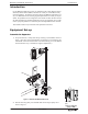
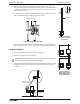
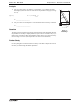
Model No. ME-9892 Equipment Set-up 3. Select one of the holes on the pendulum rod: either the center hole or the end hole. Also select a side of the pendulum: either the catcher or the bumper. Thread the attachment screw into the hole as shown in Figure 3. Screw it all the way in so it is loosely captured. 4. Thread the screw into the end of the RMS shaft. Align the pendulum rod with the tabs on the pulley as shown in Figure 4. Tighten the screw.
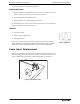
Ballistic Pendulum Accessory 4. Foam Insert Replacement Return pendulum to its normal hanging position. Prepare the Sensor 1. Connect the RMS to a PASPORT interface. If you will be using a computer, connect the interface to it and start your data collection software. 2. Set the sampling rate of the RMS to 40 Hz. 3. Prepare a graph to show angular position versus time.
Model No. ME-9892 Experiment 1: Ballistic Pendulum Experiment 1: Ballistic Pendulum Theory The ballistic pendulum has historically been used to measure the launch velocity of a high speed projectile. In this experiment, a projectile launcher fires a steel ball (of mass m ball) at a launch velocity, V 0. The ball is caught by a pendulum of mass m pend.
B a l li s t ic P e n d u l u m A c c e ss o r y Experiment 1: Ballistic Pendulum 3. Launch the ball so that it is caught in pendulum. 4. After the pendulum has swung out and back, stop data collection. 5. Note the maximum angular displacement measured by the RMS. Record it in Table 1.1. Trial 1 6. Repeat steps 1 through 5 several times. Trial 3 7. Calculate the average maximum displacement, max. Trial 4 Table 1.
Model No. ME-9892 Experiment 1: Ballistic Pendulum Analysis 1. Use your value of max, the distance r, and Equation 1.5 to calculate the maximum height (h) that the center of mass rises as the pendulum swings up (see Figure 1.3). (eq. 1.5) h = r (1 - cos (max)) qmax r x h = _____________________ 2. h Use your value of h and Equation 1.4 to calculate the launch velocity of the ball.
Ballistic Pendulum Accessory Experiment 2: Conservation of Momentum and Energy Experiment 2: Conservation of Momentum and Energy Background In this experiment you will analyze the angular collision between a ball and a physical pendulum. You will compare the rotational momentum of the ball before the collision to the rotational momentum of the pendulum-ball system after the collision. Both rotational momenta are measured about the pendulum’s pivot point.
Model No. ME-9892 Experiment 2: Conservation of Momentum and Energy Procedure 1. Load the launcher and push the ball in to the third (fastest) position. 2. Move the pendulum into the vertical position. If it does not stay that way by itself, hold it very lightly with one finger. 3. Start data collection. 4. Launch the ball so that it is caught by pendulum. 5. After the pendulum has swung out and back, stop data collection. 6. Note the maximum angular displacement measured by the RMS.
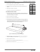
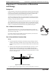
Ballistic Pendulum Accessory 2. Experiment 2: Conservation of Momentum and Energy Clamp the RMS on the mounting rod so that the pendulum can rotate in a horizontal plane (see Figure 2.3). Clamped-on pulley Hanging mass Figure 2.3: Setup for determining rotational inertia 3. Clamp a pulley to the RMS and set up a string and hanging mass (approximately 20 g to 30 g) as shown in Figure 2.3. Wind the string a few times around the middle step of the three-step pulley.
Model No. ME-9892 9. Experiment 2: Conservation of Momentum and Energy Calculate the torque () applied to the pulley by the string. = R pulley F T 10. Calculate the rotation inertia (I) of the pendulum-ball system using the rotational form of Newton’s 2nd Law: = I I = _____________________ Analysis 1. Calculate the initial angular momentum of the ball (L launch) just before the collision. The angular momentum is calculated about the pendulum pivot. L launch = m ball V launch 2.
Ballistic Pendulum Accessory Experiment 2: Conservation of Momentum and Energy 3. Compare the kinetic energy of the ball before the collision to the kinetic energy of the pendulum-ball system just after the collision. Was energy conserved in the collision? 4. What was the gain in potential energy of the pendulum (not including the ball)? What was the purpose of the counterweight? 5.
Model No. ME-9892 5. Experiment 2: Conservation of Momentum and Energy Perform the analysis for energy and momentum as before. What is the kinetic energy of the ball immediately after the collision? Why? When you calculate the gain in potential energy, remember that h is the change in height of the center of mass of the pendulum, not including the ball. Is this a perfectly elastic collision? What is the percentage of the kinetic energy lost (converted to thermal energy) during the collision? 6.
Ballistic Pendulum Accessory Experiment 2: Conservation of Momentum and Energy Further Study VI: Horizontal Collision Repeat the experiment with the apparatus in one of the configurations shown in Figure 2.6 and 2.7 using parts from the Mini Rotational Accessory (ME-8968) and a second three-step pulley. Use two sliding masses to balance the system with the ball in the catcher. Add the disk and (optionally) the ring to increase the moment of inertial.
Model No. ME-9892 Technical Support Technical Support For assistance with any PASCO product, contact PASCO at: Address: PASCO scientific 10101 Foothills Blvd. Roseville, CA 95747-7100 Phone: 916-462-8384 (worldwide) 877-373-0300 (U.S.) Web: www.pasco.com Email: support@pasco.com Limited Warranty For a description of the product warranty, see the PASCO catalog. Copyright The PASCO scientific Ballistic Pendulum Accessory Instruction Manual is copyrighted with all rights reserved.