Instruction Manual 012-07227G *012-07227* Basic Electrostatics System ES-9080A
Basic Electrostatics System 012-07227G ES-9080A Table of Contents Equipment List.............................................................................................. 3 Introduction................................................................................................... 4 Equipment Description .......................................................................... 5 - 10 Electrometer .....................................................................................................
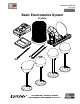
ES-9080A 012-07227G Basic Electrostatics System Basic Electrostatics System ES-9080A Equipment List 1 3 2 4 5 6 7 5 Included Equipment 1. Basic Electrometer (cables not shown) Model Number* ES-9078A 2. Electrostatics Voltage Source (cable and AC adapter not shown) ES-9077 3. Basic Variable Capacitor (cable not shown) ES-9079 4. Faraday Ice Pail and Shield ES-9042A 5. Charge Producers (2) and Proof Plane (1) ES-9075B 6. Conductive Spheres (2) ES-9059B 7.
Basic Electrostatics System ES-9080A *Use Model Numbers to expedite replacement orders. Additional Equipment PASCO data acquisition Interface and software See PASCO catalog Charge, Equipotential, and Field Mapper ES-9060 Introduction Demonstrations of electrostatic phenomenon have traditionally been limited to the simplest experiments, using the most elementary equipment, because of problems with technique and apparatus.
ES-9080A 012-07227G Basic Electrostatics System day can cause charge to easily build up in any moving object, including people. Minimize all movement when demonstrating on a very dry day. • Practice - Nothing can ruin the instructive value of a demonstration more than failure due to a demonstrator’s unfamiliarity with the equipment and procedure.
Basic Electrostatics System ES-9080A With these features, you’ll find that your electrostatics demonstrations and labs are easier to perform and, with quantitative data, are more informative.
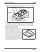
ES-9080A 012-07227G Basic Electrostatics System Variable Capacitor (ES-9079) The PASCO experimental variable capacitor consists of two conductivel plates, 20 cm in diameter, which can be adjusted to various separations. The movable plate is mounted on a calibrated slide which gives the plate separation directly in centimeters. Binding posts on each plate are provided for electrical connection.
Basic Electrostatics System ES-9080A • Avoid touching the neck during normal use. The oils from your hands will provide a path for charges to leak off. If you experience a lot of leakage, wash the white non-conductive neck with soap and water, rinsing generously; the leakage should disappear. Occasionally clean the disk surfaces with alcohol. • When you first use the charge producers, or just after cleaning, they may not produce charges readily.
ES-9080A 012-07227G Basic Electrostatics System Figure 7 shows the recommended method for using the proof plane to sample charge on a conductive sphere. Proof plane IS tangent to the surface of the conductor. Proof plane IS NOT tangent to the surface of the conductor.
Basic Electrostatics System ES-9080A To prevent stray charges from producing erroneous results, it is extremely important that the Faraday Ice Pail be momentarily grounded prior to starting any experiment. The demonstrator must also be continually grounded while performing an experiment. The Charge Producers are used as charged objects to lower into the ice pail. The Proof Plane is used to sample surface charge densities.
ES-9080A 012-07227G Basic Electrostatics System NOTE: When handling the conductive shapes, take care to keep each shape and nonconductive rod free of dirt, grease, and fingerprints to minimize leakage of charge from the shapes. Five binding posts allow the voltage source and/or the electrometer to be connected to components. NOTE: The proof planes can be used to test for charge polarity on conductors of any shape.
Basic Electrostatics System ES-9080A 5. Use the push button to set the voltage to the desired range. The range setting refers to the voltage input required to produce a full-scale meter deflection (e.g., a setting of 30 means that a full-scale meter deflection indicates a voltage of 30 volts). Important Points for General Operation: 1. Between measurements, always press the ZERO button to discharge all current from the electrometer. 2. Shorting the test leads together is insufficient.
ES-9080A 012-07227G Basic Electrostatics System Demonstration 1: Faraday Ice Pail and Charge Production Equipment Required: Electrometer (ES-9078A) Faraday Ice Pail (ES-9042A) Charge Producers (ES-9057B) Signal Input Cable (test leads) Earth ground connection Proof plane (optional) Suggestions for Introducing the Experiment Start by showing that the electrometer is directly measuring potential difference by connecting a battery to it and measuring its voltage.
Basic Electrostatics System ES-9080A Before beginning any experiment using the ice pail, the pail must be momentarily grounded. When the ice pail is connected to the electrometer, and the electrometer is connected to an earth-ground, simply press the ZERO button whenever you need to discharge both the pail and the electrometer.
ES-9080A 012-07227G Basic Electrostatics System • Before inserting the charged disk in the ice pail, make sure you’re touching the grounded shield. 4. Carefully insert the charged object into the ice pail, all the way to the lower half of the pail, but without letting it touch the pail. Note the electrometer reading. 5. Remove the object and again note the electrometer reading. If the handle never touched the pail, the reading must be zero.
Basic Electrostatics System ES-9080A 5. Remove one charge producer and note the electrometer reading. Replace the charge producer and remove the other. Note the electrometer readings. Using the magnitude and polarity of the measurements, comment on conservation of charge. Extra Things to Try 1. Try repeating Procedure 1A with the opposite charged wand. 2. Try rubbing the white charge producer with a proof plane, then measure the magnitude and polarity of the charges produced. 3.
ES-9080A 012-07227G Basic Electrostatics System Demonstration 2: Charge Distribution Equipment Required: Electrometer (ES-9078A) Faraday Ice Pail (ES-9042A) Electrostatic Voltage Source (ES-9077) Proof Plane Conductive Spheres, 13 cm (ES-9059B) (2) Signal Input cable (Test leads) Earth ground connection (patch cord) Conductive Shapes (ES-9061) Equipment Setup Sampling sphere Charged sphere Conical shape Hollow sphere Figure 2.
Basic Electrostatics System ES-9080A However, by not grounding the proof plane (and by not letting it touch the ice pail), the charge on the surface is not depleted. That charge which the proof plane removed for one measurement is always returned to the surface when the next sampling is made. NOTE: When the disk of the proof plane touches the surface being sampled, it essentially becomes part of the surface.
ES-9080A 012-07227G Basic Electrostatics System Conductive Conical Shape 1. Remove the two conducting spheres. Connect the conductive conical shape to the +2000 VDC port on the Electrostatics Voltage Source. 2. Use the proof plane to sample charge at the larger rounded end and then at the narrow end. Analysis Proof plane + + + + + + 1. Which end of the conical shape has the higher charge density? 2. Why? + + + + + + + + + + + Conductive conical shape Conductive Hollow Sphere 1.
Basic Electrostatics System 20 ES-9080A ®
ES-9080A 012-07227G Basic Electrostatics System Demonstration 3: Capacitance and Dielectrics Equipment Required: Electrometer (ES-9078A) Faraday Ice Pail (ES-9042A)l Charge Producers (ES-9057B) Proof Planes (ES-9057B) Electrostatic Voltage Source (ES-9077) Signal Input cable (Test leads) 13 cm Conductive Spheres (2) (ES-9059B) Variable Capacitor (ES-9042A) Capacitor (about 30 pF) (ES-9043) Sheet of dielectric material (See Table 3.
Basic Electrostatics System ES-9080A Procedure 3A: Measuring the Electrometer’s Capacitance Use this procedure to measure a precise value of the capacitance provided by the electrometer and all cables connected to it. If you are interested in qualitative, rather than quantitative experiments, this procedure is not necessary. When a capacitor of known capacitance C is charged by a known voltage V, the charge in it is given by Q=CV.
ES-9080A 012-07227G Basic Electrostatics System voltage source. Take care to place the capacitor sufficiently far away from the sphere and the voltage source, to prevent it from being charged by induction. Electrometer To AC power adapter Electrostatics Voltage Source Figure 3.2: Demonstration Setup 2. Press the ZERO button to remove any residual charge from the electrometer and the plates of the capacitor. 3. Set the plate separation to about 2 mm.
Basic Electrostatics System ES-9080A 5. Double the plate separation to 4 mm and repeat the procedure. What happens to the potential now? Compare the values to the previous case. Alligator clip To AC power adapter Figure 3.3a: Demonstration Setup 3B.2: Q Measured, C Variable, V Constant 1. Figure 3.3a above shows the equipment set up. The Basic Variable Capacitor has an initial plate separation of 6 cm and is connected to the +2000 VDC port on the voltage source.
ES-9080A 012-07227G Basic Electrostatics System port on the voltage source. The Faraday Ice Pail is connected to the electrometer and the electrometer is grounded to earth (i.e., through the COM port on the voltage source.). To AC power adapter Figure 3.3b: Demonstration Setup 2. Keep the plate separation constant and change the potential across the plates by changing the setting of the voltage source. You have to move the connecting cable from the +3000 V to the +2000 V port.
Basic Electrostatics System ES-9080A 3B.4: V Measured, C Variable, Q Constant 1. Figure 3.4 shows the equipment set up. The Variable Capacitor is connected to the electrometer and the electrometer is grounded to earth (through the COM port on the voltage source). The voltage source will be used to only momentarily charge the capacitor. Figure 3.4: Demonstration Setup 2. With the plate separation at 2 mm, charge the plates by momentarily connecting them across the voltage source, set at 30 V.
ES-9080A 012-07227G Basic Electrostatics System The ideal procedure to measure would be to simply slip a piece of dielectric material between a set of charged capacitor plates and then note the changes in potential. However, sliding a dielectric between the plates of the capacitor when they are too close together can generate a significant static charge that will alter the measurements.
Basic Electrostatics System ES-9080A 5. After inserting the dielectric, return the plates to the original 3 mm separation and record the new electrometer reading, Vf. 6. Pull the plates apart again, and lift and carefully remove the dielectric sheet. 7. Return the plates to the original 3 mm separation and check that the electrometer reading agrees with the original Vi reading.
ES-9080A 012-07227G Basic Electrostatics System After some algebra and rearranging, you find that CE Vi –Vf + Cp V C p ------- = --------------------------------------------i Cp Cp Vf where the ratio C´p/Cp is the dielectric coefficient : Ad C p = ----------- = ------Cp O Ad Table 3.1: Some Dielectric Coefficients Material Vacuum 1 Air 1.00059 Polystyrene 2.6 Paper 3.7 Pyrex 4.7 Mica 5.4 Porcelain 6.
Basic Electrostatics System ES-9080A 3D.1: Capacitors in Series Make sure all capacitors are uncharged before connecting them. (Use a short wire to momentarily short each one.) 1. Set up the series circuit, as shown in Figure 3.7a. 2. Plug in to the 30 VDC output on the Voltage Source. Close switch A to charge capacitor C1. 3. Using the known value of C1, calculate the initial amount of charge on C1. Let’s call it Qo. (Remember Q = CV.) 4. Throw the switch to position B. C1 and C2 are now in series. 5.
ES-9080A 012-07227G Basic Electrostatics System Demonstration 4: Charging and Discharging Capacitors Equipment Required: Electrometer (ES-9078A) Faraday Ice Pail (ES-9042A) Power Amplifier (CI-6552A) Signal Input cable (Test leads) Capacitors, 200-400 F Resistors, (10-90 k; 10-1000 ) Computer with PASCO interface DataStudio® software Introduction The purpose of this demonstration is to investigate how the voltages across a capacitor and a resistor vary as the capacitor charges and discharges,
Basic Electrostatics System ES-9080A 2. Set up the circuit shown in Figure 4.1, where the resistor and the capacitor are connected in series to the voltage source, set at 30 VDC. The electrometer output goes to one of the analog channels of the PASCO interface . Use a single-pole double-throw switch. signal output red lead double-throw switch electrometer interface signal black lead Figure 4.1: Experimental Setup and Circuit 3. Set up your experiment display in the computer to plot voltage vs. time.
ES-9080A 012-07227G Basic Electrostatics System the voltage across (and the charge on) the capacitor decreases with time according to the l RC equation V = V 0 e . After a time t = RC (one time constant), the voltage across the capacitor decreases to 37% its maximum value. 3. Determine how much is 37% of the total voltage and locate where in the discharging plot this value has been reached. How long a time since the start of discharging did it take to reach this value? (Use the smart cursor tools!) 4.
Basic Electrostatics System ES-9080A a resistance of 1000 he electrometer is reading the voltage across the capacitor, and it is also connected to one of the analog channels of the PASCO interface. 2. With the DataStudio software, create a display of voltage vs. time for the readings of the electrometer. 3. Set the signal generator to produce a positive square wave of maximum around 4 volts and of frequency 0.45 Hz. Set the signal generator to AUTO.
ES-9080A 012-07227G Basic Electrostatics System Appendix A: Copyright and Warranty Information Copyright Notice The PASCO scientific 012-07227G Basic Electrostatics System Manual is copyrighted and all rights reserved. However, permission is granted to non-profit educational institutions for reproduction of any part of the 012-07227G Basic Electrostatics System Manual, providing the reproductions are used only for their laboratories and are not sold for profit.
Basic Electrostatics System ES-9080A Product End of Life Disposal Instructions: This electronic product is subject to disposal and recycling regulations that vary by country and region. It is your responsibility to recycle your electronic equipment per your local environmental laws and regulations to ensure that it will be recycled in a manner that protects human health and the environment.