Instruction Manual 012-11726A ® *012-11726* Hydraulics Structures Set ME-6984
The cover page shows the ME-6984 Hydraulics Structures model of a hydraulic boom. Pressurized fluid moves from the syringe to the hydraulic cylinder. As the piston moves out of the cylinder, it lifts the boom structure.
Table of Contents Included Items . . . . . . . . . . . . . . . . . . . . . . . . . . . . . . . . . . . . . . . . . . . . . . . . . . . . . . . . . 1 Related, Required and Recommended Equipment . . . . . . . . . . . . . . . . . . . . . . . . . . . . . 2 Introduction . . . . . . . . . . . . . . . . . . . . . . . . . . . . . . . . . . . . . . . . . . . . . . . . . . . . . . . . . . . 2 Theory . . . . . . . . . . . . . . . . . . . . . . . . . . . . . . . . . . . . . . . . . . . . . . . . . . . . . . . . . . .
Hydraulics Structures Set iv ®
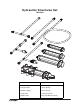
Hydraulics Structures Set ME-6984 1 2 3 6 4 5 7 8 9 ® Included Items Included Items 1. Pressure Sensor Coupler 6. 10 mL Syringe 2. Syringe Coupler 7. 20 mL Syringe 3. Extension Tubing 8. 60 mL Syringe 4. Check Valve 9. Hydraulic Cylinder 5.
Hydraulics Structures Set Introduction The ME-6984 Hydraulics Structures Set is designed to be used with parts from the PASCO Structures System*. ME-6985 Flexible I-Beams ME-6992A Advanced Structures Set ME-6987 Flat Beams ME-6993 Truss Set Members ME-6989 Physics Structures Set ME-6997 Full Round Connectors ME-6990 Truss Set ME-6999A Angle Connectors ME-6991 Bridge Set ME-7009 Cast Beam Structures Set *See the PASCO catalog or Web site at www.pasco.
Model No. ME-6984 Theory Theory Hydraulics is a topic in applied science and engineering that deals with the mechanical properties of liquids. Pneumatics is a topic that deals with the study and application of the use of pressurized gas to affect mechanical motion. Blaise Pascal described the behavior of a fluid (gas or liquid) in a closed container. Pressure applied to an enclosed fluid is transmitted undiminished to every part of the fluid, as well as to the walls of the container.
Hydraulics Structures Set Operation Couplers Pressure Sensor Coupler The pressure sensor coupler has a “T” shape. The shorter arms of the “T” have a male luer lock at one end and a female luer lock at the other. The longer arm of the “T” has an inline quick connector at the end for connecting to the pressure port on a pressure sensor. Push the inline quick connector onto the pressure port, and turn the quick connector clockwise (left to right) until the connector locks in place.
Model No. ME-6984 Operation the piston of the smaller syringe than it is to push on the piston of the larger syringe.
Hydraulics Structures Set Adding Load Cells Using a Liquid Instead of a Gas Fill a syringe with a liquid. Connect the syringe to the syringe coupler. Push the piston slowly to force liquid from the syringe into the syringe coupler until all the air is pushed out of the coupler. Finally, connect a second syringe (or the hydraulic cylinder) with the piston all the way in to the liquid filled syringe coupler.
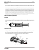
Model No. ME-6984 Hydraulic Boom Hydraulic Boom Half Round The O-ring Drive Belt loops from the Drive Wheel to the Three Step Pulley on the Rotary Motion Sensor.
Hydraulics Structures Set Hy d r a u l i c B o o m D e ta i l s Hydraulic Boom Details • Put the medium axle through a trunnion hole on the hydraulic cylinder. Medium Axle Detail • Use collets and thumbscrews on both sides of the hydraulic cylinder to position the cylinder at the middle of the axle. • Use thumbscrews to attach the medium axle to the half round connectors.
Model No. ME-6984 Fork Lift Fork Lift Yellow Cord Full Round #4 #2 Yellow Cord #3 Sliding Connector #3 Axle (Long) Sliding Connector #3 Cord Tensioning Clip D Half Round #4 #1 A #2 #5 Cord #5 Full Round #4 3 X4 C #4 B Hooked Mass #5 Axle (Medium) Axle (Medium) #3 A. Put a short axle through the longer hole in the piston cap. C. Place large slotted masses at the end of the base as a counterweight.
Hydraulics Structures Set Fo r k L i f t D e ta i l s Fork Lift Details Axles and Hydraulic Cylinder Details Piston Cap #1 #1 Axle (Short) Half Round Hydraulic Cylinder #2 Collet Axle (Medium) Thumbscrew #4 Boom Axle Details Collet Axle (Long) #2 #1 #4 #1 Short axle goes through the longer hole on the piston cap.
M o d e l N o . M E- 6 9 8 4 S c i s s o r s L if t Scissors Lift Use a thumbscrew to attach the foam core board. Foam core board (not included) Sliding Connector Axle (Medium) Hooked Mass Sliding Connector Half Round A #2 Straight Connector The sliding connector clamps onto the collet. Collet Foam Core Board Detail Axle (Medium) Collet Full Round #5 Flat Round #5 B Extra Equipment Model Hooked Mass Set SE-8759 Yellow Cord (2 pack) ME-9876 Foam core board n.a.
Hydraulics Structures Set Ideal Gas Law Introduction The Ideal Gas Law Apparatus, TD-8596A, allows simultaneous measurements of temperature and pressure of a gas as it is compressed. A low thermal mass thermistor is built into the base of the syringe to measure temperature changes inside the syringe. The response time is around 0.5 second. The plunger is equipped with a mechanical stop that protects the thermistor, and also allows for a predetermined change in volume.
Model No. ME-6984 Ideal Gas Law Procedure Set the plunger for a volume of 40 cubic centimeters (cc). Hold the base of the IGL Apparatus firmly against a sturdy horizontal surface. Ideal Gas Law Apparatus TD-8596A Pressure Sensor Coupler sidearm Temperature Connector plug Syringe Coupler Pressure/Temperature Sensor PS-2146 To PASport Interface PASport Extension Cable PS-2500 Slap down on the plunger with the palm of your hand to fully compress the gas inside the syringe.
Hydraulics Structures Set Spares Part Numbers Spares Part Numbers ME-6985 Flexible I-Beam Set ME-6997 Full Round (XYZ) Connectors #5 Flexible Beam (24 cm) - 16 Full Round Connector - 6 #4 Flexible Beam (17 cm) - 16 Flat Connector - 6 #3 Flexible Beam (11.5 cm) - 16 PAStrack Connector* - 6 ME-6986 Structures Rod Clamp (2 pack) ME-6987 Flat Structures Members ME-6998A Axle Spares 1/2 by 1/4 by 1/4 Spacer - 12 Flat 3 x 4 Beam (19 cm) - 16 “O” Ring - 12 Flat #4 Beam (17 cm) - 16 Axle, Short (10.
Model No. ME-6984 Technical Support Technical Support For assistance with any PASCO product, contact PASCO at: Address: PASCO scientific 10101 Foothills Blvd. Roseville, CA 95747-7100 Phone: 916-786-3800 (worldwide) 800-772-8700 (U.S.) Fax: (916) 786-7565 Web: www.pasco.com Email: support@pasco.com For more information about the Hydraulics Structures Set and the latest revision of this Instruction Manual, visit: www.pasco.
Hydraulics Structures Set 16 Technical Support ®