Instruction Manual and Experiment Guide for the PASCO scientific Model ME-8930 012-06734A 09/98 SMART TIMER Pla © 1998 PASCO scientific ne 4 $7.
Smart Timer 012–06734A
01206734A Smart Timer Table of Contents Section Page Table of Contents ..........................................................................................................................i Copyright, Warranty, and Equipment Return ................................................................................ ii Introduction ................................................................................................................................. 1 Equipment................................
Copyright, Warranty, and Equipment Return PleaseFeel free to duplicate this manual subject to the copyright restrictions below. Copyright Notice The PASCO scientific 012-06734A Smart Timer manual is copyrighted and all rights reserved. However, permission is granted to non-profit educational institutions for reproduction of any part of the manual providing the reproductions are used only for their laboratories and are not sold for profit.
012–06734A Smart Timer Introduction The PASCO ME-8930 Smart Timer is an accurate, versatile digital timer and measurement system for the student laboratory. The Smart Timer offers 0.1 ms timing resolution and an easy-to-use memory function. The Smart Timer measures several types of events detected with PASCO’s digital sensors, including speed and acceleration using standard photogates.
Smart Timer In One Gate Mode, a single photogate lets you measure the time, velocity, or acceleration of a fence as it passes through the photogate. Two photogates are used for collision experiments using one or two carts or for experiments where the velocity of a cart must be measured at two different points. In Two Gate Mode, two photogates are used and the time to travel between the two can be measured. This mode can also be used to measure time of flight using the ME-6810 Time-of-Flight Accessory.
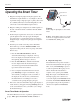
012–06734A Smart Timer Equipment Included: Smart Timer Smart Timer Picket Fences (2) 9 VDC adapter liquid crystal display mode illustrations connector for 9VDC adapter (side panel)) Pla ne 4 battery compartment (bottom panel) on/off switch (side panel) input channel 2 touchpad keys input channel 1 9 VDC adapter 5 cm fence 1 cm flag 1 cm fence Included equipment Smart Timer Picket Fence Smart Timer Picket Fence Figure 1 Smart Timer Picket Fences 3
Smart Timer Operating the Smart Timer 012–06734A 4 ne Pla input channel 2 input channel 1 1. Plug the ¼-inch phone plug from the photogate into the Smart Timer’s input channel 1 or 2 (see Figure 2). For all experiments using a single photogate or pulley, either of the two available jacks may be used interchangeably. For all other modes see the individual descriptions below. 2.
012–06734A Smart Timer 5
Smart Timer summary of the mode suggested for a given experimental activity can be found on page 5 (Quick Cross-Reference for Suggested Activities and Smart Timer Modes). Refer to the timing diagrams in Table 1 (pages 8 and 9) for a detailed look at how the Smart Timers times events on its input(s) and an explanation of how speed and acceleration calculations are performed internally. The following are detailed descriptions of the Smart Timer’s modes of operation.
012–06734A cleared and the “*” reappears. This RESET-START-STOP sequence is repeated for each new elapsed time. Whenever the “*” is not showing, the mode may be changed. Using the Alternate Timing Function: Connect an appropriate accessory to input channel #1 or #2. Enter Stopwatch mode and press the Start/Stop key. The Smart Timer will beep and a “*” will appear on the second line of the LCD. At this time the accessory will be powered.
Table 1.
Acceleration One Gate Linear Pulley Angular Pulley Two Gates 30 seconds Counts 60 seconds 5 minutes Test Manual One Gate * The key sequences shown are valid in the initial or power-on situation only.
Smart Timer Pulley (rad/s): The Smart Timer will measure the speed of a pulley passing through a photogate in units of radians/second. One measurement will be taken each time the Start/ Stop switch is pressed. The Smart Timer cannot differentiate between clockwise and counterclockwise directions. Note that, as in many other modes, if a “*” shows in the first character position of the second line, the Smart Timer is actively waiting for an external timing event to occur.
012–06734A Smart Timer timing interval. If you wish to stop the count during a timing interval, press Start/ Stop. The display will freeze the current count and the “*” will disappear from the first column. At this time you may select a new measurement or start a new timing interval. The maximum counting rate for any of the counting modes is 5,000 counts per second and the maximum count is 9,999,999.
Smart Timer Caring for the Smart Timer • Do not use a pointed object (such as a pen) to press the keypad buttons. Wrap the Smart Timer separately when transporting it with other items. The transparent covering over the keypad can be creased by a fingernail or other sharp object. • Clean the keypad with a soft cloth and mild detergent, avoiding hard rubbing of the transparent window. • Do not leave the Smart Timer exposed to direct sunlight except for brief periods.
012–06734A Smart Timer Time-of-Flight Accessory (ME-6810): The Timer-of-Flight Accessory facilitates the accurate measurement of the flight time of a ball launched by a PASCO projectile launcher. See page 33 (Time of Flight and Initial Velocity and Figure 9.1) for details of the setup. Free Fall Adapter (ME-9207B): The Free Fall Adapter facilitates easy and accurate measurements of the acceleration of gravity.
Smart Timer 14 012–06734A
012–06734A Smart Timer Experiment One: Acceleration Due to Gravity EQUIPMENT AND MATERIALS REQUIRED Smart Timer (ME-8930) Photogate (ME-9498A) Smart Timer Picket Fence Purpose The purpose is to determine the acceleration due to the Earth’s gravity. Theory The accepted value for the acceleration due to gravity on the Earth’s surface is 9.8 m/s2. With the Smart Timer, the acceleration due to Earth’s gravity can be quickly determined experimentally.
Smart Timer 012–06734A 2. Insert the plug of the photogate into channel 1 or 2 of the Smart Timer, and set up the Smart Timer to measure Time, Fence. 3. Hold the Smart Timer Picket Fence in a position so it will drop vertically through the photogate and so the 5 cm fence will block the photogate beam as the fence drops through the photogate. Note: Three conditions must be met for greatest accuracy: 1.
012–06734A Smart Timer Experiment Two: Newtons Second Law EQUIPMENT AND MATERIALS REQUIRED Smart Timer (ME-8930) Dynamics Cart (ME-9430 or ME-9454) Dynamics Cart Track (ME-9429A) 500 gram bar mass Super Pulley (ME-9450) Photogate (ME-9498A) Photogate Bracket (part no. 003-04662) Mass Hanger and Mass Set (ME-9348) Ohaus Triple-Beam Balance (SE-8707) or similar Physics String (SE-8050) Purpose The purpose is to verify Newton’s Second Law, F = ma.
Smart Timer 012–06734A 5. Place the Dynamics Cart on the track, attach a string to the hole in the end of the cart, and tie a mass hanger on the other end of the string. The string must be just long enough so the cart hits the end stop before the mass hanger reaches the floor. 6. Pull the cart back until the mass hanger reaches the pulley. Make a test run to determine how much mass is required on the mass hanger so that the cart takes about 2 seconds to complete the run.
012–06734A Smart Timer Experiment Three: Conservation of Momentum In Collisions EQUIPMENT AND MATERIALS REQUIRED Smart Timer (ME-8930) Collision Cart with mass (2) (ME-9454) Dynamics Cart Track (ME-9429A) (2) Photogate (ME-9498A) (2) Photogate Bracket (Part No. 003-04662) (2) Smart Timer Picket Fence balance Purpose The purpose of this experiment is to show that momentum is conserved in collisions.
Smart Timer 012–06734A 3. Set up the Smart Timer to measure Speed: collision (cm/s). Press Smart Timer. to activate the ➤ Note: If the flags of both carts do not go through the photogate beams twice, the Smart Timer will not complete the timing cycle and display velocities automatically. You will need to push to stop timing. The completed timing measurements will be displayed, and the uncompleted measurements will be registered as 0. Press or to view the velocities from photogate 2.
012–06734A Smart Timer Analysis 1. For each of the cases, calculate the momentum of each cart before the collision. Record the results in Table 3.2. 2. For each of the cases, calculate the total momentum of both carts before the collision. Record the results in Table 3.2. 3. For each of the cases, calculate the total momentum of both carts after the collision. Record the results in Table 3.2. 4.
Smart Timer 012–06734A Part B—Elastic Collisions Set up the carts so the magnetic ends face each other, so the carts will repel each other when they collide. Record the data in Tables 3.3 and 3.4. Equal Masses a. Place one cart at rest in the middle of the track. Give the other cart an initial velocity toward the cart at rest. b. Start both carts at opposite ends of the track at approximately the same speed.
012–06734A Smart Timer Table 3.4 Results p1 Before p2 Before p1 After p2 After PTOTAL Before PTOTAL After % of Difference Trial 1 Trial 2 Trial 3 Trial 4 Trial 5 Trial 6 Trial 7 Questions 1. Kinetic energy is not conserved in inelastic collisions but it is conserved in ideal elastic collisions. For one of the collisions, calculate the percentage of the kinetic energy that is lost in the collision. Was kinetic energy conserved? Explain your results.
Smart Timer 24 012–06734A
012–06734A Smart Timer Experiment Four: Rotational Inertia of a Disk and Ring EQUIPMENT REQUIRED Rotating Platform (ME-8951) Rotational Inertia Accessory (ME-8953) Smart Pulley (ME-9387) Smart Timer (ME-8930) Ohaus Triple-Beam Balance (DE-8707) or similar paper clips (for masses < 1 g) calipers Purpose The purpose of this experiment is to find the rotational inertia of a ring and a disk experimentally and to verify that these values correspond to the calculated theoretical values.
Smart Timer 012–06734A To find the rotational inertia experimentally, a known torque is applied to the object and the resulting angular acceleration is measured. Since t = Ia, τ I = α where a is the angular acceleration, which is equal to a/r, and t is the torque caused by the weight hanging from the thread that is wrapped around the base of the apparatus. τ = rT where r is the radius of the 3-Step Pulley about which the thread is wound and T is the tension in the thread when the apparatus is rotating.
012–06734A Smart Timer Setup 1. Place the disk directly on the center shaft as shown in Figure 4.3. The side of the disk that has the indentation for the ring should be up. 2. Place the ring on the disk, seating it in this indentation. 3. Mount the Smart Pulley to the base and connect it to channel 1 or 2 of the Smart Timer. Procedure Measurements for the Theoretical Rotational Inertia 1. Weigh the ring and disk to find their masses and record these masses in Table 4.1. 2.
Smart Timer 012–06734A least three times and record the average values for weight of the hanging mass and acceleration in Table 4.2. 3. Using calipers, measure the diameter of the pulley about which the thread is wrapped and calculate the radius. 4. Since in step 2, the disk is rotating as well as the ring, it is necessary to determine the acceleration and the rotational inertia of the disk by itself.
012–06734A Smart Timer Calculations Record the results of the following calculations in Table 4.3. 1. Subtract the “friction mass” from the hanging mass used to accelerate the apparatus to determine the mass, m, to be used in the equations. 2. Calculate the experimental value of the rotational inertia of the ring and disk together. 3. Calculate the experimental value of the rotational inertia of the disk alone. 4.
Smart Timer 30 012–06734A
012–06734A Smart Timer Other Suggested Experiments Note: The following experiments are in copy-ready form in the manual for the Dynamics Cart Accessory Track Set (manual number 012-05035) • Acceleration Down an Incline (Experiment 8): Use a Photogate and the Smart Timer instead of a stop watch (Figure 5.1). Adjust the height of the Photogate so the light path is intersected with the 5 cm fence of the Smart to Timer fences. Set up the Smart Timer to measure Acceleration, One Gate.
Smart Timer 012–06734A • Oscillations on an Incline (Experiment 4): Use a photogate and the Smart Timer instead of a stop watch, and use the ME-9471 Picket Fence (part number 648-04704), not the Smart Timer Picket Fence (Figure 7.1). Set up the Smart Timer to measure Time, Pendulum. Start the cart oscillations, and Press activate the Smart Timer to measure the period of oscillation. spring ME-9471 Picket Fence Photogate Head to Smart Timer Photogate Mounting Bracket Figure 7.
012–06734A Smart Timer Note: The following experiment is in copy-ready form in the manuals for the Mini Launcher (manual number 012-05479) and the Ballistic Pendulum/ Projectile Launcher (manual number 012-05375) • Projectile Motion Using Photogates ( Experiment 2): Use the Smart Timer instead of a computer and IDS Timer software, and set the experiment up as directed in the experiment. Plug the photogates into the Smart Timer as shown in Figure 8.1, and set up the Smart Timer to measure Time, Two Gates.
Smart Timer • Determining the acceleration due to gravity (g) with the Free Fall Adapter (ME-9207B) Insert the plug of the Free Fall Adapter into channel 1 or 2 of the Smart Timer (Figure 10.1) Set up the Stopwatch mode of the Smart once. The Smart Timer. Press Timer is now activated and will record the time the interval between the release of the ball and the contact of the ball with the receptor pad of the Free Fall Adapter.
012–06734A Smart Timer Technical Support Feedback Contacting Technical Support If you have any comments about the product or manual, please let us know. If you have any suggestions on alternate experiments or find a problem in the manual, please tell us. PASCO appreciates any customer feedback. Your input helps us evaluate and improve our product.