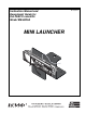
012-09562A Instruction Manual and Experiment Guide for the PASCO scientific Model ME-6825A MINI LAUNCHER 90 80 70 60 DO NO TP PISUSH TO N FINWITH GE R! 50 WE SA AR GLFETY WHASSE EN S IN US E. 40 3 0 20 10 0 10 20 Th ir Lo d Cli ng ck Ra ng e 30 40 CA UT Se c Me ond diu Cli m R ck ang e ION Fir Sh st Cli o c rt R k ang ! DO e DO NOT WN LOO BA K RR EL .
012-09562A Mini Launcher Table of Contents Section Page Introduction ....................................................................................................... 1 Equipment ......................................................................................................... 2 General Operation Of The Mini Launcher .......................................................... 3 Installation Of The Optional Photogate Bracket ..................................................
012-09562A Mini Launcher Introduction The PASCO Mini Launcher has been designed for projectile experiments and demonstrations. The only additional equipment required is a C-clamp or ME-9376B Universal Table Clamp for clamping the Launcher to a table.
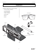
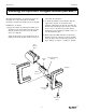
Mini Launcher 012-09562A Equipment The ME-6825 Mini Launcher includes the following: • Launcher and Base (Assembled) • (2) 16mm Steel Balls • String (to pull trigger) Safety Goggles • Collision Attachment • Safety Goggles • Pushrod • Manual Launcher Trigger Collision Attachment 90 80 70 60 DO NO TP PISUSH TO N FINWITH GE R! 50 WE SA AR GLFETY WHASSE EN S IN US E.
012-09562A Mini Launcher General Operation of the Mini Launcher ➀ Ready - Always wear safety goggles when you are in a room where the Mini Launcher is being used. - Place the ball in the barrel. Push the ball down the barrel with the pushrod until the trigger catches the piston. One audible click indicates that the piston is cocked in the shortest range setting, two clicks indicate the medium range and three clicks set the piston on the long range setting.
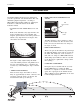
Mini Launcher 012-09562A Installing the Optional Photogate Bracket (ME-6821) vided with the photogates. The Photogate Bracket is an optional accessory for mounting one or two photogates on the Mini Launcher to measure the muzzle velocity of the ball. ➁ To mount the bracket to the Launcher, align the square nut in the slot on the bottom of the Launcher and slide the nut into the slot.
012-09562A Mini Launcher Installing the 2-Dimensional Collision Attachment The two dimensional Collision Attachment consists of 2 screws, 2 nuts, and a flat plastic bar. It is used with the Mini Launcher to hold a second ball in front of the muzzle so the launched ball will collide with the second ball, creating a 2-dimensional collision.
Mini Launcher 012-09562A Launch Positions Clamp base to table. Mount launcher as shown to shoot onto table. The square nut that the Launcher pivots around should be slid to the front of the launcher. Ball is launched at table level. When you change the angle of the launcher, the launch position does not change. Clamp base to table. Mount launcher as shown to shoot onto table. Ball is launched from a height above table level. Clamp base to a vertical rod. Clamp base to side edge of table.
012-05479B Mini Launcher Experiment 1: Projectile Motion EQUIPMENT NEEDED: – – – – – Mini Launcher and steel ball Plumb bob Meter stick Carbon paper White paper Purpose The purpose of this experiment is to predict and verify the range of a ball launched at an angle. The initial velocity of the ball is determined by shooting it horizontally and measuring the range and the height of the Launcher. Figure 1.
Mini Launcher 012-05479B Procedure Part A: Determining the Initial Velocity of the Ball ➀ Put the ball into the Mini Launcher and cock it to the long range position. Fire one shot to locate where the ball hits the floor. At this position, tape a piece of white paper to the floor. Place a piece of carbon paper (carbon-side down) on top of this paper and tape it down. When the ball hits the floor, it will leave a mark on the white paper. ➁ Fire about ten shots.
012-05479B Mini Launcher (Total Average Distance = Distance to paper edge + Average Distance) Part B: Predicting the Range of the Ball Shot at an Angle ➀ Adjust the Mini Launcher to launch at an angle between 20 and 60 degrees above the horizontal. Record this angle in Table 1.2. ➁ Using the initial velocity and vertical distance found in the first part of this experiment, calculate the new time of flight and the new horizontal range for a projectile launched at the new angle. Record in Table 1.2.
Mini Launcher 012-05479B Part C: Predicting the Range of the Ball Shot at a Negative Angle ➀ Adjust the Mini Launcher to launch at an angle between 10 and 40 degrees below the horizontal and record this angle in Table 1.3. ➁ Using the initial velocity and vertical distance found in the first part of this experiment, calculate the new time of flight and the new horizontal range for a projectile launched at the new angle. Record in Table 1.3.
012-05479B Mini Launcher Experiment 2: Projecile Motion Using Photogates EQUIPMENT NEEDED – – – – Mini Launcher and steel ball (2) Photogates Plumb bob Carbon paper – – – – Photogate bracket Computer and Timing software Meter stick White paper Purpose The purpose of this experiment is to predict and verify the range of a ball launched at an angle. Photogates are used to determine the initial velocity of the ball.
Mini Launcher 012-05479B Procedure PART A: Determining the Initial Velocity of the Ball ➀ Put the steel ball into the Mini Launcher and cock it to the long range position. ➁ Run the timing program and set it to measure the time it takes the ball to pass through both photogates. ➂ Shoot the ball three times and take the average of these times. Record in Table 2.1. ➃ Calculate the initial speed of the ball and record it in Table 2.1. The distance between the photogates is 10 cm. Table 2.
012-05479B Mini Launcher Table 2.2 Confirming the Predicted Range Angle above or below horizontal = ______________ Horizontal distance to paper edge = ____________ Calculated time of flight= ____________ Predicted Range = ____________ Trial Number Distance from Edge of Paper 1 2 3 4 5 6 7 8 9 10 Average Total Average Distance Analysis ➀ Calculate the Total Average Distance. Record in Table 2.2.
Mini Launcher 012-05479B Notes 14 ®
012-05479B Mini Launcher Experiment 3: Projectile Range Versus Angle EQUIPMENT NEEDED – Mini Launcher and steel ball – Measuring tape or meter stick – Graph paper – Plumb bob – Carbon paper – White paper Purpose The purpose of this experiment is to find how the range of the ball depends on the angle at which it is launched. The angle that gives the greatest range is determined for two cases: launching on level ground and launching off a table.
Mini Launcher 012-05479B where yo is the initial height of the ball and y is the position of the ball when it hits the floor. Setup ➀ Clamp the Mini Launcher near one end of a sturdy table with the Launcher aimed so the ball will land on the table. The square nut in the T-slot should be positioned near the muzzle. ➁ Adjust the angle of the Mini Launcher to ten degrees. ➂ Put the steel ball into the Mini Launcher and cock it to the chosen position.
012-05479B Mini Launcher ➄ Increase the angle by 10 degrees and repeat all the steps. ➅ Repeat for angles up to and including 80 degrees. SHOOTING OFF THE TABLE Clamp the Mini Launcher as shown in Fig 3.4 so that the ball will hit the floor. Repeat steps 1 through 6 and record the data in Table 3.2. You can use a plumb bob to find the point directly beneath the launch position of the ball. Analysis ➀ Find the average of the five distances in each case Àand Figure 3.4: Setup record in Tables 3.1 and 3.
Mini Launcher 012-05479B Notes 18 ®
012-05479B Mini Launcher Experiment 4: Projectile Path EQUIPMENT NEEDED – – – – Mini Launcher and steel ball – Measuring tape or meter stick Carbon paper – White paper Movable vertical target board (Must reach from floor to muzzle) Graph paper Purpose The purpose of this experiment is to find how the vertical distance the ball drops is related to the horizontal distance the ball travels when launched horizontally from a table.
Mini Launcher 012-05479B (carbon side down) over the white paper. Procedure ➀ Measure the vertical height from the floor to the muzzle and record in Table 4.1. Mark this height on the target. ➁ Measure the horizontal distance from the muzzle of the Mini Launcher to the target and record in Table 4.1. ➂ Shoot the ball. ➃ Move the target about 5 cm closer to the Launcher. ➄ Repeat Steps 2 through 4 until the ball strikes the target about 10 cm below the muzzle height. Table 4.
012-05479B Mini Launcher Table 4.2 Initial Speed Slope of graph Initial speed from slope Time of flight Initial speed from x, y Percent Difference Questions ➀ Was the line straight? What does this tell you about the relationship between y and x? ➁ If you plotted y vs. x, how would the graph differ from the y vs.
Mini Launcher 012-05479B Notes 22 ®
012-05479B Mini Launcher Experiment 5: Conservation of Energy EQUIPMENT NEEDED – – – – Mini Launcher and steel ball – Plumb bob Measuring tape or meter stick – White paper (optional) 2 Photogates and Photogate Bracket – Carbon paper (optional) Timing System Purpose The purpose of this experiment is to show that the kinetic energy of a ball shot straight up is transformed into potential energy.
Mini Launcher 012-05479B PART I: Determining the Initial Velocity of the Ball (without photogates) ➀ Put the steel ball into the Mini Launcher and cock it to the chosen range position. Fire one shot to locate where the ball hits the floor. At this position, tape a piece of white paper to the floor. Place a piece of carbon paper (carbon-side down) on top of this paper and tape it down. When the ball hits the floor, it will leave a mark on the white paper. ➁ Fire about ten shots.
012-05479B Mini Launcher ALTERNATE METHOD FOR DETERMINING THE INITIAL VELOCITY OF THE BALL (USING PHOTOGATES) ➀ Attach the photogate bracket to the Launcher and attach two photogates to the bracket. Plug the photogates into a computer or other timer. ➁ Adjust the angle of the Mini Launcher to 90 degrees (straight up). ➂ Put the steel ball into the Mini Launcher and cock it to the chosen range. ➃ Run the timing program and set it to measure the time between the ball blocking the two photogates.
Mini Launcher 012-05479B Table 5.
012-05479B Mini Launcher Experiment 6: Conservation of Momentum In Two Dimensions EQUIPMENT NEEDED – – – – Mini Launcher, 2 steel balls and Collision Attachment – Plumb bob Meter stick – Protractor Butcher paper – Tape to make collision inelastic Stand to hold ball – Carbon paper Purpose The purpose of this experiment is to show that the momentum is conserved in two dimensions for elastic and inelastic collisions. Theory A ball is shot toward another ball which is initially at rest.
Mini Launcher 012-05479B Setup ➀ Clamp the Mini Launcher near one end of a sturdy table with the Launcher aimed inward toward the table. Mount the launcher in the top hole of the bracket. ➁ Adjust the angle of the Mini Launcher to zero degrees so the ball will be shot off horizontally onto the table. Fire a test shot to determine the range. ➂ Place a piece of butcher paper on the table. The paper must extend to the base of the Launcher. ➃ Mount the Collision Attachment on the Launcher. See Figure 6.2.
012-05479B Mini Launcher PERFORM THE FOLLOWING THREE STEPS FOR THE ELASTIC COLLISION AND THEN REPEAT THESE THREE STEPS FOR THE INELASTIC COLLISION: ➃ For the x-direction, check that the momentum before equals the momentum after the collision. To do this, use the lengths for the momentums and calculate the x-components using the angles. Record the results in Tables 6.1 and 6.2. ➄ For the y-direction, check that the momenta for the two balls are equal and opposite, thus canceling each other.
Mini Launcher 012-05479B Notes 30 ®
012-05479B Mini Launcher Experiment 7: Varying Angle To Maximize Height on a Wall EQUIPMENT NEEDED – Mini Launcher and steel ball – Measuring tape or meter stick – White paper – Plumb bob – Carbon paper – Board to protect wall Purpose The purpose of this experiment is to find the launch angle which will maximize the height at which the ball strikes a vertical wall for a ball launched at a fixed horizontal distance from the wall.
Mini Launcher 012-05479B ➃ Tape a piece of white paper to the board in the region where the ball is hitting. Then cover the white paper with a piece of carbon paper. Procedure ➀ Shoot the ball at various angles and pinpoint exactly which angle gives the maximum height by checking the marks on the paper. ➁ Measure the angle that produces the maximum height and record in Table 7.1. ➂ Measure the maximum height and record in Table 7.1.
012-05479B Mini Launcher Experiment 8 (Demo): Do 30⋅ and 60⋅ Give the Same Range? EQUIPMENT NEEDED -Mini Launcher and steel ball Purpose The purpose of this demonstration is to show that the range of a ball launched at 30° is the same as one launched at 60° if the ball is shot on a level surface.
Mini Launcher 012-05479B Experiment 9 (Demo): Simultaneously Shoot Two Balls Horizontally at Different Speeds EQUIPMENT NEEDED – 2 Mini Launchers and 2 steel balls Purpose The purpose of this demonstration is to show that regardless of the initial speed of the balls launched horizontally off a table, the balls will hit the floor at the same time. Theory Two balls are launched horizontally from the same table (from the same height, y). The muzzle speeds of the two balls are different.
012-05479B Mini Launcher Experiment 10 (Demo): Shooting Through Hoops EQUIPMENT NEEDED – – – – Mini Launcher and steel ball (2) Photogates Meter stick (optional) Computer with Timing software – (5) Ring clamps on stands – Photogate Bracket – (2) Meter stick Purpose The purpose of this demonstration is to show that the path of a ball launched horizontally from a table is parabolic.
Mini Launcher 012-05479B ➂ Lay the 2-meter stick on the floor in a straight line away from the Launcher. ➃ Measure off each set of x and y and place a ring clamp on a stand at each position (See Figure 10.1). If possible it is best to adjust the last two ring stands at an angle from the vertical so the ball will not have to pass through them at an oblique angle. A cup may be placed at the end of the path to catch the ball. ➄ Shoot the ball through the rings.
Model No. ME-6825A Technical Support Technical Support For assistance with any PASCO product, contact PASCO at: Address: PASCO scientific 10101 Foothills Blvd. Roseville, CA 95747-7100 Phone: 916-786-3800 (worldwide) 800-772-8700 (U.S) Fax: (916) 786-3292 Web: www.pasco.com Email: techsupp@pasco.com Limited Warranty For a description of the product warranty, see the PASCO catalog. Copyright The PASCO scientific 012-09562A Mini Launcher Instruction Manual is copyrighted with all rights reserved.