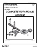
012-05293F Complete Rotational System Instruction Manual and Experiment Guide for the PASCO scientific Model ME-8950A 012-05293F 01/09 COMPLETE ROTATIONAL SYSTEM TIA ER L IN RY NA SO TIO ES TA CC RO A ROTATIONAL INERTIA ACCESSORY © PASCO scientific ® www.pasco.
Complete Rotational System 012-05293F
012-05293F Complete Rotational System Table of Contents Section Page Copyright Warranty, and Equipment Return................................................... ii Introduction...................................................................................................... 1 • Description • About this Manual • Computer Timing Equipment ....................................................................................................... 2 Miscellaneous Supplies ......................................
Complete Rotational System 012-05293F Copyright, Warranty and Equipment Return Please—Feel free to duplicate this manual subject to the copyright restrictions below. Copyright Notice Equipment Return The PASCO scientific Model ME-8950A Complete Rotational System manual is copyrighted and all rights reserved.
012-05293F Complete Rotational System Introduction PASCO’s Complete Rotational System provides a full range of experiments in centripetal force and rotational dynamics. The system consists of three separate components: The ME-8953 Rotational Inertia Accessory includes a disk and a metal ring. The disk can be mounted to the rotating base in a variety of positions and at any radius. This accessory requires the Rotating Platform (ME-8951) to operate.
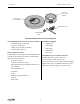
Complete Rotational System 012-05293F Equipment accessory mounting rod aluminum rotating platform photogate mounting rod 300g square mass (2) with thumbscrews and square nuts low-profile thumbscrew assemblies (2) rotating vertical shaft with 10-hole pulley cast iron "A" base "E" rings (2, 1 extra) ME-8951 Rotating Platform Equipment The ME-8951 Rotating Platform includes the following: - two additional low-profile screws and square nuts to act as stops for the square mass in the Conservation of A
012-05293F Complete Rotational System mass ring (12.7 cm outside diameter) rotational disk (25.4 cm diameter) TIA ER L IN RY NA SO TIO ES TA CC RO A ROTATIONAL INERTIA ACCESSORY Super Pulley and rod rotating platform adapter ME-8953 Rotational Inertia Accessory Equipment The ME-8953 Rotational Inertia Accessory includes: Miscellaneous Supplies: - disk with bearings in the center - graph paper - ring (12.
Complete Rotational System 012-05293F Assembly ME-8951 Rotating Platform Assembling the Rotating Platform 1. Insert the cylindrical end of the shaft into the bearings on the top-side of the A-shaped iron base. Secure the shaft in place by inserting the "E" ring in the slot at the bottom of the shaft. See Figure 1. 2. Mount the track to the shaft and tighten the thumb screw against the flat side of the “D” on the shaft. See Figure 1.
Complete Rotational System 24 012-05293F 15 22 21 20 19 18 13 14 15 16 17 24 0 1 2 3 4 5 6 7 8 9 10 11 13 4 3 2 1 6 9 23 5 14 7 1 8 22 6 16 8 0 7 21 7 17 9 1 6 16 20 8 18 10 2 5 15 19 10 21 19 11 3 4 12 18 11 22 20 12 4 3 11 17 9 300g square mass 13 5 2 10 rotating platform (rotated 90° as shown) 12 14 "A" base 23 rotating platform 300g square mass 15 16 17 Figure 2: Leveling the Base Some experiments (such as the Centri
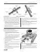
Complete Rotational System 012-05293F 6. When the Photogate Head is powered by a computer interface, you can tell when the photogate is 10-spoke blocked by watching the LED indicator on pulley on the photogate. vertical nylon thumbscrew shaft pulley mounting rod To use the Super Pulley and Photogate Head with the Pulley Mounting Rod: 1. Attach the Super Pulley -- and the Photogate Head if needed -- to the Pulley Mounting Rod. 2.
012-05293F Complete Rotational System holes for thread nylon thumbscrew Side Post Assembly Assemble the side post as shown in Figure 6: 1. Insert the thumb screw at the bottom of the side post and attach the square nut. single length of thread (30cm long) 2. Using a string about 30 cm long, tie the string around the screw head on the top of the side post. Then thread the other end of the string down through one of the holes in the top of the side post and then back up through the other hole.
Complete Rotational System 012-05293F rotational disk bearing of rotational disk TIA ER L IN RY NA SO TIO ES TA ACC O R platform adapter square nut "D" hole on top surface of rotational platform adapter rotating platform Figure 8: Rotational Inertia Accessory Including Platform Adapter Assembly The rotating disk can be mounted in a variety of positions using any of the four holes on the rotation disk. • Two “D” holes exist on the edge of the disk, located at 180° from one another.
012-05293F Complete Rotational System Experiment 1: Conservation of Angular Momentum (Projectile Version) EQUIPMENT NEEDED - Rotating Platform (ME-8951) - Projectile Launcher (ME-6800) - Projectile Collision Accessory (ME-6815) - Photogate/Pulley System (ME-6838) - DataStudio Software - PASCO Interface (see Note) - Rubber band - White paper and carbon paper - Thread - Meter Stick (SE-6895) - Mass and Hanger Set (ME-8967) - Calipers (SF-8711) Note: If you are using a PASPORT interface, you will also nee
Complete Rotational System 012-05293F Iω v 0 = ---------mb R To find the rotational inertia experimentally, a known torque is applied to the object and the resulting angular acceleration is measured.
012-05293F Complete Rotational System Part I: Determining the initial velocity of the ball Projectile Launcher Setup LONG RANGE 90 MEDIUM RANGE SHORT RANGE Yellow Band in Window Indicates Range. 80 70 CAUTION! CAUTION! NOT LOOK DODO NOT LOOK DOWN BARREL! DOWN THE BARREL. 60 50 1. Clamp the Projectile Launcher to a sturdy table near one end of the table. 2. Adjust the angle of the Projectile Launcher to zero degrees so the ball will be shot off horizontally. See Figure 1.3.
Complete Rotational System 012-05293F Trial Number Time 1 2 3 Average Time Initial Velocity Table 1.2 Initial Speed Using Photogates 5. The distance between the Photogates is 10 cm. Calculate the initial speed and record it in Table 1.2 and Table 1.4. Part II: Conservation of Angular Momentum Setup rubber band side view of rotating platform rubber band end view of rotating platform "catcher" tab of "catcher" against platform Figure 1.4: Attaching the Catcher to the Track 1.
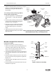
012-05293F Complete Rotational System Part III: Determining the Rotational Inertia Setup 1. Attach a Photogate with a pulley and mounting rod to the base using the black rod. 2. Connect the Photogate to a PASCO interface and connect the interface to a computer. 3. Wind a thread around the middle step pulley on the center shaft and pass the thread over the pulley.
Complete Rotational System 012-05293F Measure the Radius 1. Using calipers, measure the diameter of the step pulley about which the thread is wrapped and calculate the radius. 2. Record the radius in Table 1.4. Analysis 1. Calculate the average of the angular speeds in Table 1.3 and record the result in Table 1.5. 2. Calculate the rotational inertia: • Subtract the “friction mass” from the hanging mass used to accelerate the apparatus to determine the mass, m, to be used in the equations.
012-05293F Complete Rotational System Experiment 2: Rotational Inertia of a Point Mass EQUIPMENT NEEDED - DataStudio Software - PASCO Interface (see Note) - Paper clips (for masses < 1 g) - Balance Note: If you are using a PASPORT interface, you will also need a Digital Adapter (PS-2159) - Mass and Hanger Set - Photogate/Pulley System - Calipers Purpose The purpose of this experiment is to find the rotational inertia of a point mass experimentally and to verify that this value corresponds to the calcu
Complete Rotational System 012-05293F Once the linear acceleration of the mass (m) is determined, the torque and the angular acceleration can be obtained for the calculation of the rotational inertia. Setup 1. Level the rotating platform. 2. Attach the square mass (point mass) to the track on the rotating platform at any radius you wish. 3. Mount the Photogate/Pulley system to the base and connect the photogate through an interface to a computer. See Figure 2.2. 4.
012-05293F Complete Rotational System 5. If the velocity increases or decreases as the platform turns, stop monitoring data, stop the platform, and adjust the amount of mass on the thread by adding or removing a paper clip. 6. Repeat the process until the velocity stays constant as the mass falls. 7. Measure the mass on the end of the thread and record it as the ’Friction Mass’ in Table 2.2.
Complete Rotational System 012-05293F 4. Subtract the rotational inertia of the apparatus from the combined rotational inertia of the point mass and apparatus. This will be the rotational inertia of the point mass alone. Record in Table 2.3. 5. Calculate the theoretical value of the rotational inertia of the point mass. Record in Table 2.3. 6. Use a percent difference to compare the experimental value to the theoretical value. Record in Table 2.3. Table 2.
012-05293F Complete Rotational System Experiment 3: Centripetal Force EQUIPMENT NEEDED - Centripetal Force Accessory (ME-8952) - Stopwatch - Graph paper (2 sheets) - String - Rotating Platform (ME-8951) - Balance - Mass and Hanger Set Purpose The purpose of this experiment is to study the effects of varying the mass of the object, the radius of the circle, and the centripetal force on an object rotating in a circular path.
Complete Rotational System 012-05293F side post assembly string center post assembly clamp-on pulley rotating platform hanging mass "A" base Figure 3.1: Centripetal Force Apparatus 2. Attach the clamp-on pulley to the end of the track nearer to the hanging object. Attach a string to the hanging object and hang a known mass over the clamp-on pulley. Record this mass in Table 3.1. This establishes the constant centripetal force. 3.
012-05293F Complete Rotational System 5. Calculate the centripetal force from the slope and record in Table 3.2. 6. Calculate the percent difference between the two values found for the centripetal force and record in Table 3.2. Table 3.2: Results (varying raduis) Centripetal Force = mg Centripetal Force From Slope Percent Difference Part II: Vary Force (constant radius and mass) The radius of rotation and the mass of the hanging object will be held constant for this part of the experiment. 1.
Complete Rotational System 012-05293F Table 3.3: Varying the Centripetal Force Mass of the object = Radius = Slope from graph = Mass Over Pulley Centripetal Force = mg Period (T) 1 T2 5. Calculate the mass of the object from the slope and record in Table 3.4. 6. Calculate the percent difference between the two values found for Table 3.4: Results (varying the centripetal force) the mass of the object and record in Table 3.4.
012-05293F Complete Rotational System Table 3.5: Varying the Mass of the Object Mass hanging over pulley = Centripetal Force = mg = Radius = Mass of Object Period (T) Calculated Centripetal Force % Difference Analysis 1. The weight of the mass hanging over the pulley is equal to the centripetal force applied by the spring. Calculate this force by multiplying the mass hung over the pulley by “g” and record the result at the top of Table 3.5. 2.
Complete Rotational System 012-05293F Notes: 24
012-05293F Complete Rotational System Experiment 4: Conservation of Angular Momentum Using a Point Mass EQUIPMENT REQUIRED - DataStudio Program - PASCO Interface (see Note) - Rotational Inertia Accessory (ME-8953) - Rotating Platform (ME-8951) - Photogate/Pulley System - Balance Note: If you are using a PASPORT interface, you will also need a Digital Adapter (PS-2159) Purpose A mass rotating in a circle is pulled in to a smaller radius and the new angular speed is predicted using conservation of angul
Complete Rotational System 012-05293F T rotating platform a mg "A" base hanging mass Figure 4.1: Rotational Apparatus and Free-Body Diagram Part I: Conservation of Angular Momentum Setup 1. Level the apparatus using the square on the track as shown in the leveling instructions in the Assembly Section. 2. Slide a thumb screw and square nut into the T-slot on the top of the track and tighten it down at about the 5 cm mark. This will act as a stop for the sliding square mass. See Figure 4.2.
012-05293F Complete Rotational System Procedure 1. Select ’Smart Pulley (Rotational)’ as the type of sensor. Set up a Graph display of Velocity (rad/s) versus time. 2. Hold the string just above the center post. With the square mass against the outer stop, give the track a spin using your hand. 3. Click ’Start’ to begin recording data. After about 20 data points have been taken, pull up on the string to cause the square mass to slide from the outer stop to the inner stop. 4.
Complete Rotational System 012-05293F Procedure Accounting For Friction Because the theory used to find the rotational inertia experimentally does not include friction, it will be compensated for in this experiment by finding out how much mass over the pulley it takes to overcome kinetic friction and allow the mass to drop at a constant speed. Then this “friction mass” will be subtracted from the mass used to accelerate the apparatus. 1. Start the DataStudio program.
012-05293F Complete Rotational System Analysis 1. Calculate the rotational inertias: • Subtract the “friction mass” from the hanging mass used to accelerate the apparatus to determine the mass, m, to be used in the equations. • Calculate the experimental values of the rotational inertia and record it in Table 4.3. 2. Calculate the expected (theoretical) values for the final angular velocity and record these values in Table 4.3. Table 4.
Complete Rotational System 012-05293F Notes: 30
012-05293F Complete Rotational System Experiment 5: Rotational Inertia of Disk and Ring EQUIPMENT REQUIRED - DataStudio Program - PASCO Interface (see Note) - Rotational Inertia Accessory (ME-8953) - Photogate/Pulley System - Mass and Hanger Set - Paper Clips (for masses < 1 g) - Balance - Calipers Note: If you are using a PASPORT interface, you will also need a Digital Adapter (PS-2159) Purpose The purpose of this experiment is to find the rotational inertia of a ring and a disk experimentally and to
Complete Rotational System 012-05293F where α is the angular acceleration which is equal to a/r and τ is the torque caused by the weight hanging from the thread which is wrapped around the base of the apparatus. τ = rT where r is the radius of the cylinder about which the thread is wound and T is the tension in the thread when the apparatus is rotating. Applying Newton’s Second Law for the hanging mass, m, gives (See Figure 5.
012-05293F Complete Rotational System Table 5.1: Theoretical Rotational Inertia Mass of Ring Mass of Disk Inner Radius of Ring Outer Radius of Ring Radius of Disk Measurements for the Experimental Method Accounting For Friction Because the theory used to find the rotational inertia experimentally does not include friction, it will be compensated for in this experiment by finding out how much mass over the pulley it takes to overcome kinetic friction and allow the mass to drop at a constant speed.
Complete Rotational System 012-05293F Measure the Radius 1. Using calipers, measure the diameter of the cylinder about which the thread is wrapped and calculate the radius. Record in Table 5.2.
012-05293F Complete Rotational System 7. Calculate the theoretical value of the rotational inertia of the disk about its center of mass and about its diameter. 8. Use a percent difference to compare the experimental values to the theoretical values. Table 5.
Complete Rotational System 012-05293F Notes: 36
012-05293F Complete Rotational System Experiment 6: Rotational Inertia of Disk Off-Axis (Fixed/Rotating) EQUIPMENT REQUIRED - DataStudio Program - PASCO Interface (See Note) - Rotational Inertia Accessory (ME-8953) - Photogate/Pulley System - Calipers - Mass and Hanger Set - Paper Clips (for masses < 1 g) - Balance Note: If you are using a PASPORT interface, you will also need a Digital Adapter (PS-2159) Purpose The purpose of this experiment is to find the rotational inertia of a disk about an axis p
Complete Rotational System 012-05293F Applying Newton’s Second Law for the hanging mass, m, gives (See Figure 6.1) ΣF = mg – T = ma rotating platform rotational disk T platform adapter a "A" base hanging mass mg Figure 6.1: Rotational Apparatus and Free-Body Diagram Solving for the tension in the thread gives: T = m(g – a ) Once the linear acceleration of the mass (m) is determined, the torque and the angular acceleration can be obtained for the calculation of the rotational inertia. Setup 1.
012-05293F Complete Rotational System Table 6.1: Theoretical Rotational Inertia Mass of Disk Radius of Disk Distance Between Parallel Axis Measurements For the Experimental Method Accounting For Friction Because the theory used to find the rotational inertia experimentally does not include friction, it will be compensated for in this experiment by finding out how much mass over the pulley it takes to overcome kinetic friction and allow the mass to drop at a constant speed.
Complete Rotational System 012-05293F Measure the Radius 1. Using calipers, measure the diameter of the cylinder about which the thread is wrapped and calculate the radius. Record in Table 6.2.
012-05293F Complete Rotational System Experiment 7: Conservation of Angular Momentum EQUIPMENT REQUIRED - DataStudio Program - Rotational Inertia Accessory (ME-8953) - Rotating Platform (ME-8951) Note: If you are using a PASPORT interface, you will also need a Digital Adapter (PS-2159) - PASCO Interface - Balance - Photogate/Pulley System Purpose A non-rotating ring is dropped onto a rotating disk and the final angular speed of the system is compared with the value predicted using conservation of angu
Complete Rotational System 012-05293F Procedure 1. Hold the ring just above the center of the disk. Give the disk a spin using your hand. 2. Start recording data. After about 25 data points have been taken, drop the ring onto the spinning disk. See Figure 7.2. 3. Continue to take data after the collision for a few seconds and then stop recording data. dropped ring photogate head rotational disk "A" base Figure 7.2: Experiment Setup 4. Examine the Graph display of the rotational speed versus time.
012-05293F Complete Rotational System Questions 1. Does the experimental result for the angular speed agree with the theory? 2. What percentage of the rotational kinetic energy is lost during the collision? Calculate this and record the results in Table 7.1.
Complete Rotational System 012-05293F Notes: 44
012-05293F Complete Rotational System Technical Support Feed-Back Contacting Technical Support If you have any comments about this product or this manual please let us know. If you have any suggestions on alternate experiments or find a problem in the manual please tell us. PASCO appreciates any customer feedback. Your input helps us evaluate and improve our product.