
User's Manual
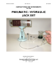


Pneumatic / Hydraulic Jack Set SE-8764A
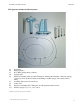
Turn clockwise while holding the T-fitting
with your finger. Do not over-tighten.
Do NOT lower and
tighten the syringe collar until the
hose T-fitting is attached
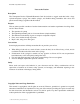
Insert the piston (b) into the 60 cc main body syringe (c). Push it in all the way.
Install the 6 cc syringe onto the sidearm of the T-fitting (between the two one-way valves) of the main
hose assembly (e). Do not over tighten.
Now attach the assembly hose (f) to the main assembly hose (e) by fitting the ¼ turn valve (g) onto the
free end of the main assembly hose. Do not over tighten.
Main hose assembly (e)
Hose assembly (f) with ¼ turn valve (g)
(If the apparatus is to be used with air or other gases, the setup is complete. If the unit is to be used
with water as a hydraulic system, or if an understanding of the action of the pump is desired, continue
with the following steps.)
Place the unattached ends of the tubing (e) and (f) in the bottom of a beaker or similar container of
water.
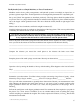
The valve should be opened (on) with the handle in line with tubing, as shown in the diagram. Pull out
the small syringe to the limit of the measuring graduation marks. Push it all the way in. Repeat this
several times, watching the movement of the fluid and air bubbles. Make sure the ends of the tubing do
not come out of the water.
Describe the fluid movement during the pull stroke. ________________________________________
Describe the movement during the push stroke. ____________________________________________
© 2001 James M. Housley, Transparent Devices
4