Instruction Manual Manual No. 012-06053B Rotary Motion Sensor Model No.
Rotary Motion Sensor Model No. CI-6538 Table of Contents Equipment List........................................................... 3 Optional Accessories ................................................. 4-5 Mini-Rotational Accessory ............................................................................................................4 Linear Motion Accessory...............................................................................................................4 Chaos Accessory ..............
Model No. CI-6538 Rotary Motion Sensor Rotary Motion Sensor Model No. CI-6538 Equipment List 1 2 3 Included Equipment 1. Rotary Motion Sensor Replacement Model Number* CI-6539 2. O-ring NA 3. Ziplock Bag NA *Use Replacement Model Numbers to expedite replacement orders.
Rotary Motion Sensor Model No. CI-6538 Optional Accessories Mini-Rotational Accessory - The PASCO CI-6691 Mini-Rotational Accessory is used to perform rotational inertia experiments, conservation of angular momentum experiments, and pendulum experiments. Included are an aluminum disk, a steel ring, a long thin rod, and two brass masses which can be attached at any point on the thin rod to act as point masses. (For instructions on attaching this accessory, see “Equipment Setup” in this manual).
Model No. CI-6538 Rotary Motion Sensor to the side of the RMS to provide variable magnetic damping. (For instructions on using this accessory, see “Equipment Setup” in this manual). The Chaos Accessory is a driven damped physical pendulum. Various types of phase plots can be made as the driving frequency, driving amplitude, initial conditions, and the amount of damping are varied.
Rotary Motion Sensor Model No. CI-6538 IDS Mount Accessory The PASCO CI-6692 IDS Mount Accessory is a bracket that allows the Rotary Motion Sensor to be attached to the Introductory Dynamics System tracks. 3-Step Pulley Accessory (CI-6693) The PASCO CI-6693 3-step Pulley Accessory includes an additional pulley for mounting a 3-step Pulley on each end of the Rotary Motion Sensor rotating shaft. It also includes an oring.
Model No. CI-6538 Rotary Motion Sensor Introduction The PASCO CI-6538 Rotary Motion Sensor is a bidirectional position sensor designed for use with the PASCO ScienceWorkshop™ 750 Interface. It contains an optical encoder which gives a maximum of 1440 counts per revolution (360 degrees) of the Rotary Motion Sensor shaft. The resolution can be set in the ScienceWorkshop software to 360 or 1440 times per revolution (1 degree or 1/4 degree). The direction of rotation is also sensed.
Rotary Motion Sensor Model No. CI-6538 General Setup Options 1) Mounting the Rotary Motion Sensor (RMS) a) Mounting the RMS on a Support Rod The Rotary Motion Sensor can be mounted on a support rod using the supplied rod clamp. The rod clamp can be mounted in three different locations on the Rotary Motion Sensor: at the end opposite the cable and on either side of the case. A Phillips screwdriver is required to remove the two screws that hold the rod clamp on the Rotary Motion Sensor case.
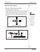
Model No. CI-6538 Rotary Motion Sensor thin rod 3-step Pulley space RMS support rod Figure 4: Mounting the Rotary Motion Sensor with the thin rod from the mini-Rotational Accessory b) Mounting the RMS to a Dynamics Track The Rotary Motion Sensor can be mounted to a Dynamics Track using the IDS Mount Accessory. To mount the RMS to the track, do the following: a) Slide the square nut into the insert on the side of the track.
Rotary Motion Sensor Model No. CI-6538 The Rotary Motion Sensor can be used as a “Smart Pulley” in this configuration by threading a string over the Rotary Motion Sensor pulley and hanging a mass on the string.
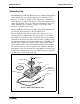
Model No. CI-6538 Rotary Motion Sensor d) Mounting the RMS to the Gyroscope The Rotary Motion Sensor can be mounted to the Gyroscope using the RMS/Gyroscope Accessory. This allows the nutation angle of the Gyroscope to be detected.
Rotary Motion Sensor Model No. CI-6538 Attaching Accessories to the Rotary Motion Sensor (RMS) a) Attaching the Mini-Rotational Accessory to the RMS To attach the thin rod to the RMS, orient the 3-step Pulley so the rod guides on the underside of the pulley face up. The 3-step Pulley and the rotating shaft on the RMS are keyed to assemble only in one position. Assemble the apparatus as illustrated.
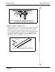
Model No. CI-6538 Rotary Motion Sensor •The end of the rod can be attached to the Rotary Motion Sensor rotating shaft to use it as a pendulum. Rotary Motion Sensor support rod rod with mass Figure 10: Using the rod as a pendulum Using the Disk and Ring For rotational inertia experiments, wrap around string attached to a mass around the 3-step pulley included with the Rotary Motion Sensor. Hang the mass over the clamp-on Super Pulley to accelerate the apparatus.
Rotary Motion Sensor Model No. CI-6538 b) Attaching the “A” Base Rotational Adapter Accessory to the RMS The drive belt links the 3step Pulley mounted on the “A” base to the 3-step Pulley on the RMS. For a one-toone correspondence, connect the two pulleys using the o-ring on the middle step of each pulley. Each revolution of the Rotating Platform or Gyroscope corresponds to one revolution of the RMS. If desired, a 5-to-1 ratio can be attained by putting the oring on the top or bottom steps.
Model No. CI-6538 Rotary Motion Sensor c) Using the Chaos Accessory with the RMS The Chaos Accessory is a driven damped physical pendulum. Various types of phase plots can be made as the driving frequency, driving amplitude, initial conditions, and amount of damping are varied.
Rotary Motion Sensor Model No. CI-6538 Using the Rotary Motion Sensor with Data Collection Software To operate the Rotary Motion Sensor, you must plug it into the ScienceWorkshop 750 interface and perform the necessary setup in DataStudio. Calibration of the sensor is not required, but optional for those who wish better accuracy. For calibration instructions, see Appendix B of this manual. 1.
Model No.
Rotary Motion Sensor Model No. CI-6538 (see Figure 1.1). Solving for the tension in the thread gives: T = m(g – a) After the angular acceleration of the mass (m) is measured, the torque and the linear acceleration can be obtained for the calculation of the rotational inertia. Experiment Setup 1. Attach a mass on each end of the rod (part of the MiniRotational Accessory) equidistant from the rod center. You may choose any radius you wish. 2.
Model No. CI-6538 Rotary Motion Sensor Procedure Part I: Measurements for the Theoretical Rotational Inertia 1. Weigh the masses to find the total mass Mtotal and record in Table 1.1. 2. Measure the distance from the axis of rotation to the center of the masses and record this radius in Table 1.1. Table 1.1:Theoretical Rotational Inertia Data Total mass Radius Part II: Measurement for the Experimental Method a) Finding the Acceleration of the Point Masses and Apparatus 1.
Rotary Motion Sensor Model No. CI-6538 b) Measure the Radius 1. Using calipers, measure the diameter of the pulley about which the thread is wrapped and calculate the radius. Record in Table 1.2. c) Finding the Acceleration of the Apparatus Alone In part IIa, “Finding the Acceleration of the Point Mass and Apparatus,” the apparatus is rotating and contributing to the rotational inertia.
Model No. CI-6538 Rotary Motion Sensor 5. Use a percent differenc to compare the experimental value to the theoretical value. Record in Table 1.3. Table 1.
Rotary Motion Sensor Model No.
Model No. CI-6538 Rotary Motion Sensor where α is the angular acceleration, which is equal to a/r (a = acceleration), and τ is the torque caused by the weight hanging from the thread that is wrapped around the base of the apparatus. τ = rT where r is the radius of the pulley about which the thread is wound, and T is the tension in the thread when the apparatus is rotating. Applying Newton’s Second Law for the hanging mass, m, gives ΣF = mg – T = ma (see Figure 2.3).
Rotary Motion Sensor Model No. CI-6538 straight down the middle of the groove on the clamp-on Super Pulley. (see Figure 2.4) Clamp-on Super Pulley 3-step Pulley thread Figure 2.4: Super Pulley position 5. Place the disk directly on the pulley as shown in Figure 2.5. mass ring 6. Place the mass ring on the disk, inserting the ring pins into the holes in the disk as shown in Figure 2.5. clamp-on Pulley Procedure Rotary Motion Sensor Measurements for the Theoretical Rotational Inertia 1.
Model No. CI-6538 Rotary Motion Sensor Measurements for the Experiment Method a) Finding the Acceleration of the Ring and Disk 1. Open DataStudio and select "Create Experiment." 2. In the Sensors list of the Experiment Setup window, click and drag a RMS Sensor icon to the first of the two consecutive digital ports that the RMS is plugged into on the interface. 3. Double click the RMS icon in Experiment Setup window to open the Sensor Properties dialog box. 4.
Rotary Motion Sensor Model No. CI-6538 c) Finding the Acceleration of the Disk Alone 1. In "Finding the Acceleration of Ring and Disk," both the disk and the ring are rotating; therefore, it is necessary to determine the acceleration and the rotational inertia of the disk by itself so this rotational inertia can be subtracted from the total, leaving only the rotational inertia of the ring. 2.
Model No.
Rotary Motion Sensor Model No. CI-6538 Setup: 1. Mount the RMS to a support rod and connect it to a computer. Place the disk directly on the pulley as shown in Figure 3.1. disk 2. Open DataStudio. 3. In the Experiment Setup window, click and drag a Rotary Motion sensor icon to the first of the two consecutive digital ports that the RMS is plugged into on the interface. RMS with 3-step Pulley support rod Figure 3.1: Setup for Dropping Ring Onto Disk 4.
Model No. CI-6538 Rotary Motion Sensor Analysis: 1. Calculate the expected (theoretical) value for the final angular velocity and record this value in Table 3.1. 2. Calculate the percent difference between the experimental and the theoretical values of the final angular velocity and record in Table 3.1. Questions: 1.
Rotary Motion Sensor Model No. CI-6538 Appendix A: Specifications Rotary Motion Sensor 30 Description 3-Step Pulley 10 mm, 29 mm, and 48 mm diameters Resolution 10 and 0.250 Accuracy +/- 0.09 degrees Maximum rotation speed 13 revs/sec at 10 resolution 3.25 revs/sec at 0.
Model No. CI-6538 Rotary Motion Sensor Appendix B: Calibration of the Rotary Motion Sensor Calibration of the CI-6538 ScienceWorkshop® Rotary Motion Sensor is not required. However, you can zero the CI-6538 Rotary Motion Sensor as follows: 1. Connect a ScienceWorkshop Rotary Motion Sensor and set the sensor to the zero position (See the instruction sheet or experiment guide provided with your Rotary Motion Sensor for instructions.) 2.
Rotary Motion Sensor Model No. CI-6538 Appendix C: Technical Support For assistance with the CI-6538 Rotary Motion Sensor or any other PASCO products, contact PASCO as follows: Address: PASCO scientific 10101 Foothills Blvd. Roseville, CA 95747-7100 32 Phone: (916) 786-3800 FAX: (916) 786-3292 Web: www.pasco.com Email: techsupp@pasco.
Model No. CI-6538 Rotary Motion Sensor Appendix D: Copyright and Warranty Information Copyright Notice The PASCO scientific 012-06053B Rotary Motion Sensor Manual is copyrighted and all rights reserved. However, permission is granted to non-profit educational institutions for reproduction of any part of the 012-06053B Rotary Motion Sensor Manual, providing the reproductions are used only for their laboratories and are not sold for profit.