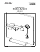
Instruction Manual 012-12876B ® *012-12876* PASCO Mechanics Statics System ME-9502
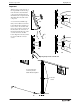
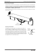
The cover page shows a a Friction Block on the Statics System Inclined Plane with a PASCO Mass Hanger from the ME-8979 Mass and Hanger Set suspended by a thread over a Small Pulley. Most of the components of the Statics System are held magnetically to the included workboard. This manual contains fifteen copy-ready experiments about the fundamentals of statics.
Table of Contents Introduction . . . . . . . . . . . . . . . . . . . . . . . . . . . . . . . . . . . . . . . . . . . . . . . . . . . . . . . . . . . 1 Equipment . . . . . . . . . . . . . . . . . . . . . . . . . . . . . . . . . . . . . . . . . . . . . . . . . . . . . . . . . . . . 1 Recommended Equipment . . . . . . . . . . . . . . . . . . . . . . . . . . . . . . . . . . . . . . . . . . . . . . . 3 Spares Package. . . . . . . . . . . . . . . . . . . . . . . . . . . . . . . . . . . . . . . . . . . . . . . .
S t a t ic s S y s t e m iv 012-12876B ®
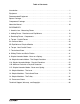
Statics System ME-9502 Introduction The study of mechanics often begins with Newton’s Laws of Motion. The first law describes the conditions for an object to maintain its state of motion. If the net force on an object is zero, the acceleration of the object is zero. If F = 0 then a = 0 The second law describes what happens if the net force on an object is not zero.
S t a t ic s S y s t e m Equipment Important When moving or removing any of the magnetically mounted components from the board, handle the component by the magnetic base rather than by the component itself. This will reduce the strain on the component. Yes A second board (available separately) can be attached to the first board with the three included connector screws. To join the boards, remove the connector screws from the threaded holes on the side of the first board.
Model No. ME-9502 R e c o m m e n d e d E q u ip m e n t * ME-9504 Spares Package Item Qty Item Qty String Tie Assembly 3 Thumbscrew 6-32 by 5/8” (for Cord Clip) 2 Torque Indicator Assembly 6 Thumbscrew 4-40 by 1/2” (for balance arm protractor) 2 Nylon Thread, spool 1 Thumbscrew 6-32 by 1/4” (for balance arm pivot) 1 Cord Tensioning Clip 2 Washer 0.
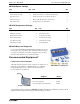
Statics System Spares Package (ME-9504) Stopwatch (ME-1234) The PASCO Stopwatch has a liquid crystal display (LCD) with two display modes. Its precision is 0.01 seconds up to 3599.99 seconds, and 1 second up to 359999 seconds. Its memory holds up to nine event times. Stop Watch Mass Balance Use a mass balance such as the OHAUS Scout Pro Balance 2000 g (SE-8757A) or the OHAUS Cent-O-Gram Balance (SE-8725).
Model No. ME-9502 Components Package (ME-9505) Components Package (ME-9505) Mounted Scale Assembly Top hook The mounted scale has four strong magnets in its base. The tube is marked in newtons (N), ounces (oz.) and millimeters (mm). The thumbnut allows the top hook to be raised or lowered in order to align the red indicator disk with the zero mark on the tube. Thumbnut Tube To zero the scale, mount the scale on the statics board. Leave the bottom hook empty. Unscrew the thumbnut a few turns.
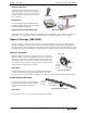
Statics System Components Package (ME-9505) Inclined Plane Assembly The Inclined Plane Assembly has four strong magnets on its back side that hold it in position on the Statics Board. CAUTION: The magnets on the Inclined Plane Assembly are not covered with protective material. Be careful to firmly hold the inclined plane when placing it on the board so that the magnets are not damaged by “snapping” against the board.
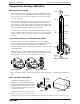
Model No. ME-9502 Components Package (ME-9505) Torque Wheel Assembly and Torque Indicator Assembly The Torque Wheel Assembly has a 5 cm radius disk with a label that has concentric circles 2 mm apart. The disk rotates freely on a ball bearing and has five holes for attaching a Torque Indicator Assembly. The Torque Indicator snaps into the hole and rotates freely. Tie a 30 cm (12”) thread to the hole in the end of each indicator. Base Tie a thread to the hole.
Statics System Components Package (ME-9505) (Imagine that the Force Wheel disk is transparent so that you can see the String Tie.) Hold the Force Wheel as shown and push the clear plastic tabs inward with your forefingers until the String Tie pops out of the Force Wheel. Base Force Wheel Remove String Tie String Tie Balance Arm Assembly The Balance Arm Assembly consists of a Beam, a Pivot, and three Protractors that can be mounted on the beam. Each protractor has a transparent Angle Indicator.
Model No. ME-9502 Components Package (ME-9505) Utility Mount Assembly Base The Utility Mount has several functions. It can support a PS-2201 5 N Load Cell, it has a rod from which you can hang the Asymmetrical Plate, and the included Cord Tensioning Clip allows you to connect a thread to the mount. The thumbscrew for the Load Cell is “captured” by a rubber O-ring so that it will not fall out of the mount.
Statics System About the Manual Asymmetrical Plate The Asymmetrical Plate is a five-sided polygon with a small hole at each corner. The Utility Mount has a slender metal rod designed to support the Asymmetrical Plate so that the plate can swing on the rod until it reaches equilibrium. Base Utility Mount About the Manual The ME-9502 Statics System provides an introduction to static mechanics.
Model No. ME-9502 E x p . 1 : H o o k e ’ s L a w — M e a s u r i n g F o r ce Exp. 1: Hooke’s Law—Measuring Force Equipment Needed Item Item Statics Board Mounted Spring Scale Mass and Hanger Set Thread Introduction Top hook At a practical level, a force is simply a push or a pull. A force is also a vector quantity that has magnitude (size) and direction. There are different ways to apply and measure a force.
Statics System Exp. 1: Hooke’s Law—Measuring Force Data Table Spring Displacement (m) Mass (kg) Uncertainty Weight (N) 0.010 m (10 mm) 0.020 m (20 mm) 0.030 m (30 mm) 0.040 m (40 mm) 0.050 m (50 mm) 0.060 m (60 mm) 0.070 m (70 mm) 0.080 m (80 mm) Calculations 1. Using the formula F = mg, where m is the mass and g is the acceleration due to gravity, calculate the weight in newtons for each trial. Record the weight in the data table.
Model No. ME-9502 Exp. 2: Adding Forces—Resultants and Equilibriants Exp. 2: Adding Forces—Resultants and Equilibriants Equipment Needed Item Item Statics Board Mounted Spring Scale Force Wheel Large and Small Pulleys Mass and Hanger Set Thread Theory In figure 2.1, Person A and Person B are pulling with forces represented by FA and FB on a car stuck in the mud. Since these forces are acting on the same point of the car, they are called concurrent forces.
Statics System Exp. 2: Adding Forces—Resultants and Equilibriants Procedure: Two Forces 1. Add or remove 0.5 g to the mass hanger. Did the force disk move away from the center position? How much can you change the mass on the mass hanger without changing where the force disk is centered? 2. What are the magnitude and direction of Fg, the gravitational force applied by the hanger, where Fg = mg? • Fg: Magnitude ________________ 3.
Model No. ME-9502 Exp. 2: Adding Forces—Resultants and Equilibriants Analysis 1. On a separate piece of graph paper, use the values you recorded in the table to construct a vector diagram for F1, F2, and FE. Choose an appropriate scale, such as 2.0 centimeters per newton, and make the length of each vector proportional to the magnitude of the force. Label each vector and indicate the magnitude of the force it represents. 2.
Statics System 16 Exp.
Model No. ME-9502 Exp. 3: Resolving Forces—Components Exp. 3: Resolving Forces—Components Equipment Needed Item Item Statics Board Mounted Spring Scale Force Wheel Pulleys (2) Mass and Hanger Set Thread Theory In experiment 2, you added concurrent forces vectorially to determine the magnitude and direction of the combined forces. In this experiment, you will do the reverse: you will find two forces which, when added together, have the same magnitude and direction as the original force.
Statics System Exp. 3: Resolving Forces—Components 3. What are the magnitudes of Fx and Fy, the x- and y-components of F? • Fx = _________________ 4. Change the magnitude and direction of the force vector F and repeat the experiment. 5. Record the magnitude and angle of the new force vector, F, and the magnitudes of Fx and Fy.
Model No. ME-9502 Exp. 3: Resolving Forces—Components Question 1. Is the force disk at equilibrium in the center of the Force Wheel? 2. Why or why not? Extensions 1. Generally it is most useful to find the components of a vector along perpendicular axes, as you did above. However, it is not necessary that the axes be perpendicular. If time permits, try setting up the equipment to find the components of a vector along non-perpendicular axes.
Statics System 20 Exp.
Model No. ME-9502 Exp. 4: Torque—Parallel Forces Exp. 4: Torque—Parallel Forces Equipment Needed Item Item Statics Board Balance Arm and Protractors Mass and Hanger Set Thread Theory A In experiment 2, you found resultants and equilibriants for concurrent forces—forces that act upon the same point. In the real world, forces are often not concurrent. They act upon different points on an object. In the figure, for example, two forces are pulling on different points of an object.
Statics System Exp. 4: Torque—Parallel Forces Procedure: Equal Distance, Equal Mass Position one of the protractors near one end the beam and tighten its thumbscrew to hold it in place. Adjust the position of the other protractor until the beam is perfectly balanced, and then tighten its thumbscrew to hold it in place. 1. Measure d1 and d2, the distances from the pivot to the center of each protractor. • d1 = _______________ • d2 = _______________ 2. Add a 50-gram mass to each mass hanger.
Model No. ME-9502 Exp. 4: Torque—Parallel Forces Data Table Case Total Mass M1 (kg) Weight F1 (N) Distance d1 (m) Torque 1 = F1 d1 Total Mass M2 (kg) Weight F2 (N) Distance d2 (m) Torque 2 = F2 d2 1 2 3 4 5 6 Questions 1. From your results, what mathematical relationship must there be between 1 and 2 in order for the beam to be balanced? 2.
Statics System 24 Exp.
Model No. ME-9502 Exp. 5A: Center of Mass Exp. 5A: Center of Mass Equipment Needed Item Item Statics Board Balance Arm and Protractors Asymmetrical Plate Thread Mass and Hanger Set Theory Gravity is a universal force; every bit of matter in the universe is attracted to every other bit of matter. Therefore, when the Balance Arm is supported by the pivot, every bit of matter in the Balance Arm is attracted to every bit of matter in the Earth.
Statics System E x p . 5 A: C e n t e r o f M a s s Level the Beam and Mark the Center of Mass Loosen the thumbscrew and adjust the beam so that the indicator marks on the pivot are aligned with the zero mark on the beam. If necessary, adjust the positions of the two protractors until the bubble in the bubble level is midway between the two lines on the level. Once the beam is balanced and level, tighten the thumbscrews to hold the protractors and beam in place.
Model No. ME-9502 • Exp. 5A: Center of Mass Recalculate the torques about the pivot point. Position Force (F = mg) Torque ( = F d) 2 3 5. Are the torques balanced? Asymmetrical Plate Replace the Balance Arm with the Force Sensor Mount. Hang the Asymmetrical Plate from the rod on the Force Sensor Mount.
Statics System 28 E x p .
Model No. ME-9502 E x p . 5 B: E q u i l i b r i u m o f P h y s i c a l B o d i e s Exp. 5B: Equilibrium of Physical Bodies Equipment Needed Item Item Statics Board Balance Arm and Protractors Pulley (1) Mounted Spring Scale Mass and Hanger Set Thread Theory F1 Any force acting on a body may produce both translational motion (movement of the center of mass of the body in the direction of the force) and rotational motion (rotation about a pivot point).
Statics System Exp. 5B: Equilibrium of Physical Bodies Data Table. Position mass (M) force (F) distance (d) torque () 1 2 3 4 — Calculations 1. Calculate and record the sum of the clockwise and counterclockwise torques. cw = _________________________ ccw = _______________________ • Are the torques balanced? 2. Calculate and record the sum of the upward and downward forces. Fup = _________________________ Fdown = _______________________ • Are the translational forces balanced? 3.
Model No. ME-9502 E x p . 5 B: E q u i l i b r i u m o f P h y s i c a l B o d i e s Data Table: Change the Origin. Position force (F) distance (d) torque () 1 2 3 4 Calculations 1. Calculate and record the sum of the clockwise and counterclockwise torques. cw = _________________________ ccw = _______________________ • Are the torques balanced? Extension Use a pulley, hanging mass, and a thread to produce an additional upward force at one end of the beam.
Statics System 32 Exp.
Model No. ME-9502 Exp. 6: Torque—Non-Parallel Forces Exp. 6: Torque—Non-Parallel Forces Equipment Needed Item Item Statics Board Balance Arm and Protractors Pulley Mounted Spring Scale Mass and Hanger Set Thread Theory In a previous experiment, you investigated torques appled to the Balance Arm and discovered that when the torques about the point of rotation are balanced, the beam remains balanced. All the forces in that experiment were perpendicular to the beam and parallel to each other.
Statics System Exp. 6: Torque—Non-Parallel Forces Suspend a mass, M2, from one protractor. Mount the Spring Scale on the Statics Board and connect it to the other protractor using a thread and a Pulley as shown. Spring Scale Protractor Beam Pulley M2 Figure 6.2: Equipment Setup Procedure d2 1. Measure d1 and d2 and record the values. 2. Record the total mass, M2, and the magnitude of the force, F2 (weight of the hanging mass).
Model No. ME-9502 Exp. 6: Torque—Non-Parallel Forces 4. Perform the calculations to determine the torque, 1, provided by the Spring Scale, and the percent difference between 1 and 2. [The percent difference is the difference of the two torques divided by the average of the two torques.] • To provide a consistent mathematical definition of torque, 1 and 2 must be determined according to the same formula. 5.
Statics System Exp. 6: Torque—Non-Parallel Forces Set Up the Torque Wheel Torque Indicator Arm Torque Wheel Remove the Balance Arm and set up the Torque Wheel on the Statics Board as shown in the diagram. Use pulleys, thread, and hanging masses to apply three torques to the wheel. Radial scale d2 d3 F1 Use the radial scale on the Torque Wheel label to measure the perpendicular distance from each line of force to the pivot point. Record the distances in the data table.
Model No. ME-9502 Exp. 7: The Inclined Plane Exp. 7: The Inclined Plane Equipment Needed Item Item Statics Board Inclined Plane and Cart Pulley (2) Mounted Spring Scale Mass and Hanger Set Thread Introduction Object Suppose you must design a ramp with a cable to hold a heavy object on an inclined ramp.
Statics System Exp. 7: The Inclined Plane The force provided by the Spring Scale, Fmeasured, equals the component of the force of gravity that is parallel to the Inclined Plane, FThe calculated component of force that is parallel to the Inclined Plane, Fcalculated, is F sin , where is the angle of the plane. 3. Adjust the angle of inclination of the Inclined Plane to each of the values shown in the table.
Model No. ME-9502 Exp. 7: The Inclined Plane Record the total mass of the mass hanger and calculate and record the weight. • total mass of mass hanger = _______________ weight of mass hanger = _________________ • How does the weight of the mass hanger compare to value of Fcalculated, the component of the cart’s weight that is parallel to the plane? (See the data table for the value at 15°.) Add a second pulley to the Statics Board and set up the Spring Balance above the pulley.
Statics System 40 Exp.
Model No. ME-9502 Exp. 8: Sliding Friction Exp. 8: Sliding Friction Equipment Needed Item Item Statics Board Inclined Plane and Friction Block Pulley Mounted Spring Scale Mass and Hanger Set Thread Theory Friction is a force between two objects that resists motion between the two objects. Static friction (or sticking friction) is friction between objects that are not moving relative to each other. For example, static friction can prevent an object from sliding down an inclined plane.
Statics System Exp. 8: Sliding Friction • If the Friction Block stops, the mass is too light. If the Friction Block accelerates, the mass is too heavy. • The weight of the hanging mass that is sufficient to pull the Friction Block at a constant speed is fk, the force of the sliding (kinetic) friction between the Friction Block and the Inclined Plane. Variables Change the following factors and measure the sliding friction force.
Model No. ME-9502 Sliding Friction on an Inclined Plane Questions 1. In trials 1 through 6, what happens to the sliding friction as the normal force increases? 2. In trials 1 through 6, what happens to the coefficient of friction as the normal force increases? 3. How does the sliding friction for the large wood surface compare to the sliding friction for the large felt surface? How does the sliding friction for the small wood surface compare to the sliding friction for the small felt surface? 4.
Statics System Sliding Friction on an Inclined Plane Procedure 1. Measure and record the weight, W, of the Friction Block. • weight, W =__________ 2. Mount the Inclined Plane on the Statics Board and set the angle, , to 15°. Set up the pulley, mass hanger, thread, and Friction Block as shown in the figure. Make sure that the thread is parallel to the Inclined Plane. The thread must be parallel to the plane. Friction Block Hanging mass Figure 8.4: Friction on an Inclined Plane Setup 3.
Model No. ME-9502 Static Friction on an Inclined Plane Static Friction on an Inclined Plane Imagine that the Friction Block is placed on the Inclined Plane, and one end of the plane is tilted upward until the parallel component of the block’s weight begins to pull the block down the plane. Static friction holds the block in place on the plane until the parallel component of the block’s weight is larger than the static friction.
Statics System 46 Static Friction on an Inclined Plane 012-12876B ®
Model No. ME-9502 Exp. 9: Simple Harmonic Motion–Mass on a Spring Exp. 9: Simple Harmonic Motion–Mass on a Spring Equipment Needed Item Item Statics Board Mounted Spring Scale Mass and Hanger Set Thread Stopwatch (ME-1234) Theory Imagine a mass hanging from a spring. At rest, the mass hangs in a position such that the spring force just balances the gravitational force on the mass (its weight).
Statics System E x p . 9 : S i m p l e H a r m o n ic M o t i o n – M a s s o n a S p r i n g 3. Pull the mass hanger down and release it smoothly. Let it oscillate a few times before taking any measurements. When the oscillations are smooth and regular, measure the time for at least ten complete oscillations (down-up-down). If possible, measure the time for as many oscillations as you can before the amplitude of the oscillations becomes too small. Record the number of oscillations and the total time.
Model No. ME-9502 Exp. 9: Simple Harmonic Motion–Mass on a Spring Extension In addition to the hanging mass, there is other mass that is oscillating up and down. The rod inside the Spring Scale moves up and down as well. A portion of the spring itself moves as the hanging mass oscillates.
Statics System S i m p l e H a r m o n i c M o t i o n – B e a m o n a S p r in g Simple Harmonic Motion–Beam on a Spring Imagine a horizontal beam that is supported by a hinge at one end and a vertical spring at the other end. If the end of the beam is pulled down, the spring exerts a restoring force, F = -kx, to return the beam to its equilibrium position. The beam will oscillate up and down with a period, Tbeam. For a mass on a spring, the period, T, is as follows: T = Hinge Beam Spring L Figure 9.
Model No. ME-9502 S i m p l e H a r m o n i c M o t i o n – B e a m o n a S p r in g In this part of the experiment you will investigate this equation for the simple harmonic motion of a beam on a spring. Procedure 1. Mount a Protractor on one end of the Balance Arm. Measure and record the total mass of the arm plus protractor. • mass, m = ____________ 2. Add the Pivot to the other end of the Balance Arm and mount the Balance Arm on the Statics Board. Spring Scale Protractor Pivot Figure 9.
Statics System S i m p l e H a r m o n i c M o t i o n – B e a m o n a S p r in g Data Table Trial Oscillations Total Time (s) Measured Period (s) Theoretical Period (s) 1 2 3 4 5 Average Measured Period (s) Questions 1. How well does the theoretical value for the period of oscillation compare to the average measured period of oscillation? 2.
Model No. ME-9502 Exp. 10: Simple Harmonic Motion–The Simple Pendulum Exp. 10: Simple Harmonic Motion–The Simple Pendulum Equipment Needed Item Item Statics Board Utility Mount and Cord Clip Thread Mass and Hanger Set Stopwatch (ME-1234) Theory Pivot point Simple harmonic motion is not limited to masses on springs. In fact, it is one of the most common and important types of motion found in nature.
Statics System Exp. 10: Simple Harmonic Motion–The Simple Pendulum Procedure 1. Place the Utility Mount near the top edge of the Statics Board. Loop a thread approximately 45 cm long through a Cord Clip and attach the Cord Clip to the mount. 2. Attach a 10 g mass to the thread and adjust the length of the thread so that the pendulum is as long as possible on the board. 3. Measure and record L, the length of the pendulum from the pivot point to the center of mass of the hanging mass.
Model No. ME-9502 Exp. 10: Simple Harmonic Motion–The Simple Pendulum Data Table Mass 1 (kg) Length 2 (m) Oscillations Total Time (s) Measured Period (s) Theoretical Period (s) Measured Period (s) Theoretical Period (s) 0.010 Average Measured Period (s) Mass 1 (kg) Length 3 (m) Oscillations Total Time (s) 0.010 Average Measured Period (s) Calculations 1. Calculate and record the Measured Period by dividing the total time by the number of oscillations. 2.
Statics System 56 Exp.
Model No. ME-9502 E x p . 1 1 A : S i m p l e H a r m o n i c M o t i o n – P h ys i c a l P e n d u l u m Exp. 11A: Simple Harmonic Motion–Physical Pendulum Equipment Needed Item Item Statics Board Balance Arm Stopwatch (ME-1234) Theory Pivot point A simple pendulum is a mass on the end of a “massless” length of string. A physical pendulum is any rigid body that pivots at some point of the body so that it can rotate freely in a vertical plane under the force of gravity.
Statics System E x p . 1 1 A : S i m p l e H a r m o n ic M o t i o n – P h y s i c a l P e n d u l u m In this part of the experiment you will investigate this equation for the period of the simple harmonic motion of a physical pendulum with a fixed distance between the pivot point and the center of mass. Procedure Pivot point 1. Move the pivot of the Balance Arm to the 170 mm mark at one end of the beam, and mount the pivot near the top of the Statics Board. 2.
Model No. ME-9502 2. E x p .
Statics System E x p . 1 1 A : S i m p l e H a r m o n ic M o t i o n – P h y s i c a l P e n d u l u m Extension: Period of Oscillation for Large Angles The motion of a physical pendulum is simple harmonic motion for small angles. When the angle becomes larger, sin .
Model No. ME-9502 E x p . 1 1 A : S i m p l e H a r m o n i c M o t i o n – P h ys i c a l P e n d u l u m 5. Stretch one of the threads from the Force Disk to the arc on the board. Arrange the thread so it is straight down from the Force Wheel, and put a mark on the arc and label it as 0°. 6. Keep the thread taut and move it so the angle relative to vertical is 5°. Put a mark on the arc and label it. 7.
Statics System 62 E x p .
Model No. ME-9502 Exp. 11B: Minimum Period of a Physical Pendulum Exp.
Statics System Exp. 11B: Minimum Period of a Physical Pendulum Procedure 1. Move the pivot of the Balance Arm to a position one centimeter (cm) above the midpoint of the beam (presumably the center of mass of the beam). Mount the pivot on the Statics Board. 2. Start the beam swinging but keep the angle of the swing reasonably small (less than 20°).. 3. Measure and record the total time for 10 oscillations. 4.
Model No. ME-9502 Exp. 11B: Minimum Period of a Physical Pendulum Calculations 1. For each distance, Lcm, calculate and record the Measured Period by dividing the total time by the number of oscillations. 2. Create a graph of Measured Period versus distance, Lcm, to determine which length gives the minimum period. • Minimum Lcm = _______________ 3.
Statics System 66 Exp.
Model No. ME-9502 Exp. 11C: Simple Harmonic Motion–Beam on a Spring Exp. 11C: Simple Harmonic Motion–Beam on a Spring Equipment Needed Item Item Statics Board Mounted Spring Scale Mass and Hanger Set Balance Arm and Protractor Stopwatch (ME-1234) Thread Theory Imagine a horizontal beam that is supported by a hinge at one end and a vertical spring at the other end. If the beam is displace, the spring exerts a restoring force, F = -kx, to return the beam to its equilibrium position.
Statics System Exp. 11C: Simple Harmonic Motion–Beam on a Spring where I is the moment of inertia and k is the spring constant. If you assume that the beam is like a rectangular-type rod, then the moment of inertia about the center of mass of the rod is: 2 1 I cm = ------ ML 12 where M is the mass and L is the length of the rod.
Model No. ME-9502 Exp. 11C: Simple Harmonic Motion–Beam on a Spring 10. Measure and record the length of the beam, L, and the distance from the pivot point to the center of mass (c.o.m.) of the beam, Lcm. 11. See the experiment Hooke’s Law to find the spring constant, k, of the Spring Scale and record its value. Calculations 1. Calculate and record the Measured Period for each trial. 2. Calculate and record the Average Measured Period for each lever arm length.
Statics System Exp. 11C: Simple Harmonic Motion–Beam on a Spring Data Table Llever (m) Oscillations Total Time (s) Measured Period (s) Theoretical Period (s) 0.060 Average Measured Period (s) 0.070 Average Measured Period (s) 0.080 Average Measured Period (s) 0.090 Average Measured Period (s) 0.100 Average Measured Period (s) Questions 70 1. How well does the theoretical value for the period of oscillation compare to the average measured period of oscillation for each trial? 2.
Model No. ME-9502 Exp. 11C: Simple Harmonic Motion–Beam on a Spring Extension • Plot a graph of period, T, versus the reciprocal of Llever.
Statics System 72 Exp.
Model No. ME-9502 Exp. 12: Simple Machines–The Lever Exp. 12: Simple Machines–The Lever Equipment Needed Item Item Statics Board Mounted Spring Scale Mass and Hanger Set Balance Arm and Protractors Large Pulley Thread Pencil or Dry Erase Marker Pen Theory The workings of a lever can be understood using the concept of torque.
Statics System Exp. 12: Simple Machines–The Lever 2. Mount a Large Pulley and Spring Scale at one end of the Balance Arm and use thread to connect the Spring Scale to the Protractor on the Balance Arm. 3. Use thread to hang a mass hanger from the other Protractor and add 200 g of mass to the hanger. 4. Adjust the Large Pulley and the Spring Scale so that the Balance Arm beam is horizontal and level. Procedure 1.
Model No. ME-9502 Exp. 12: Simple Machines–The Lever Data Table Item Trial 1 Trial 2 Item Distance hanging mass moved, d1 Mass of hanging mass, M1 Distance Spring Scale moved, d2 Weight of hanging mass, W1 Trial 1 Trial 2 Force of Spring Scale, F2 Calculations 1. Calculate and record the work done on the system as you raised the Spring Scale, where Work = F2 d2. 2.
Statics System Exp. 12: Simple Machines–The Lever A wheelbarrow is an example of a Class II Lever, and the human forearm is an example of a Class III Lever. Applied force Fulcrum Lcm Figure 12.6: Class III Lever Load When a lever is in equilibrium, the sum of the clockwise torques about the pivot point (fulcrum) is equal to the sum of the counterclockwise torques about the pivot point.
Model No. ME-9502 Exp. 13: Simple Machines–The Inclined Plane Exp. 13: Simple Machines–The Inclined Plane Equipment Needed Item Item Statics Board and Pulley Mounted Spring Scale Mass and Hanger Set Inclined Plane and Mass Cart Pencil or Dry Erase Marker Pen Thread Introduction The inclined plane, like the lever, is often used to help raise heavy objects. In a previous experiment, you analyzed this use of the inclined plane in terms of the forces that are involved.
Statics System Exp. 13: Simple Machines–The Inclined Plane 3. Measure and record the magnitude of the force, F1, exerted by the Spring Scale on the Mass Cart, and the angle of the Inclined Plane. • Force, F1 = _____________ Angle, 4. Use a pencil or dry erase marker pen to outline the base of the Spring Scale on the Statics Board. 5. Slowly raise the Spring Scale – slowly enough that there is no appreciable change in the reading on the Spring Scale. 6.
Model No. ME-9502 2. Exp. 13: Simple Machines–The Inclined Plane Slowly push the Spring Scale straight up a distance, d1 sin the height to which the Mass Cart was raised when it was on the Inclined Plane. (Raise the Spring Scale slowly so that there is no appreciable change in the reading of the Spring Scale.) Calculations 1.
Statics System 80 Exp.
Model No. ME-9502 Exp. 14: Simple Machines–The Pulley Exp. 14: Simple Machines–The Pulley Equipment Needed Item Item Statics Board and Pulley Mounted Spring Scale Large Pulley and Small Pulleys (2) Double Pulley Block Mass and Hanger Set Thread Theory In previous experiments, you used pulleys to change the direction of applied forces. However, systems of pulleys can be arranged to translate relatively small applied forces into much larger forces, much the same way as a lever or inclined plane.
Statics System 4. E x p . 1 4 : S i m p l e M a c h i n e s – Th e P u l l e y Use a pencil or dry erase marker pen to outline the base of the Spring Scale. Also mark the position of the top of the hanging mass. A B C d1 Large Pulley Outline Small Pulley Loop the thread around the pulley. Double Pulley d2 Hanging Mass Original position Figure 14.3: Pulley Systems Note that the drawings are not to scale. Allow more vertical distance between the components. 5.
Model No. ME-9502 Exp. 15: Forces on a Boom Exp. 15: Forces on a Boom Equipment Needed Item Item Statics Board Mounted Spring Scale and Pulley Balance Arm and Protractors) Thread Mass and Hanger Set Theory Boom A boom supported by a cable has a mass suspended at its upper end. The lower end of the boom is supported by a pivot.
Statics System Exp. 15: Forces on a Boom Procedure 1. 2. 3. 4. Set up the Balance Arm with the pivot at one end, a protractor at the midpoint, and a second protractor at the other end. Mount the Balance Arm in a lower corner of the Statics Board. Mount the Spring Scale and a Pulley on the board and use thread to attach the Spring Scale to the protractor at the midpoint of the beam.
Model No. ME-9502 Exp. 16: Modified Atwood’s Machine Exp. 16: Modified Atwood’s Machine Equipment Needed Item Item Statics Board Small Pulley (2) Mass and Hanger Set Thread Stopwatch Dry-erase Marker Pen or Pencil Theory Pulley The acceleration of an object depends on the net applied force and the object’s mass. In an Atwood’s Machine, the difference between two hanging masses determines the net force acting on the system of the two masses.
Statics System Exp. 16: Modified Atwood’s Machine Setup 1. Place the two Small Pulleys on the Statics Board near the top edge of the board and close to each other. Make sure that the two pulleys are level. 2. Connect a thread from one Mass Hanger to a second Mass Hanger so the hangers are suspended over the two pulleys. Pulley • NOTE: Make the thread long enough so that the heavy mass almost reaches the base of the Statics Board when the light mass is almost up to the pulley.
Model No. ME-9502 Exp. 16: Modified Atwood’s Machine Data Table 1: Constant Total Mass Trial M1 (kg) M2 (kg) M (kg) 1 0.001 2 0.002 3 0.003 4 0.004 5 0.005 t1 t2 t3 tavg atheoretical ameasured % diff. Part 2: Keep Net Force Constant 1. Put a 50-g mass on the ‘light’ (M1) mass hanger and put a 50-g mass and a 5-g mass on the ‘heavy’ (M2) mass hanger. 2. Including each 5-g mass hanger, record the total mass for M1 and the total mass for M2 in the Data Table. 3.
Statics System Exp. 16: Modified Atwood’s Machine 3. Calculate and record the percent difference of the theoretical acceleration and the measured acceleration for each trial. a theoretical – a measured % diff= --------------------------------------------------------- 100 a theoretical 4. For the Constant Total Mass data, calculate the net force (Fnet = M x g) for each trial. Plot a graph of net force (vertical axis) versus measured acceleration (horizontal axis). Questions 88 1.
Model No. ME-9502 Technical Support Technical Support For assistance with any PASCO product, contact PASCO at: Address: PASCO scientific 10101 Foothills Blvd. Roseville, CA 95747-7100 Phone: 916-786-3800 (worldwide) 800-772-8700 (U.S.) Fax: (916) 786-7565 Web: www.pasco.com Email: support@pasco.com For more information about the Statics System and the latest revision of this Instruction Manual, visit the PASCO web site and enter ME-9502 into the Search window.
S t a t ic s S y s t e m 90 T e c h n ic a l S u p p o r t 012-12876B ®