Instruction Manual with Experiment Guide and Teachers’ Notes 012-09900B ® Basic Optics System OS-8515C Ben ch 20 30 40 50 60 E N T C O M 70 P O N 80 10 80 0 9 L A M R O N 20 70 5 46 -8 S O 0 10 70 M C O 10 80 20 L A M R O N P O N E N T 60 S IC T P E O BL IC A S T A Y B RA 50 40 30 50 40 30 60 10 20 30 40 50 60 70 80 90 tics 0 Op
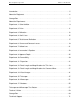
Basic Optics System T a b l e o f C o n t e n ts Introduction . . . . . . . . . . . . . . . . . . . . . . . . . . . . . . . . . . . . . . . . . . . . . . . . . . . . . . . . . . . 5 About the Equipment . . . . . . . . . . . . . . . . . . . . . . . . . . . . . . . . . . . . . . . . . . . . . . . . . . . . 6 Storage Box . . . . . . . . . . . . . . . . . . . . . . . . . . . . . . . . . . . . . . . . . . . . . . . . . . . . . . . . . . . 7 About the Experiments. . . . . . . . . . . . . . . . . . . . . . . . .
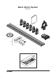
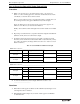
Basic Optics System OS-8515C 1 Op tics Ben ch 3 4 5 2 6 20 30 40 50 60 7 70 P O N E N T 10 80 C O M 70 L A M R O N 20 80 90 5 46 -8 S O 0 10 60 N T 70 C 10 80 20 L A M R O N O M P O N E 50 40 30 50 40 30 60 S IC T P E O BL IC A S T A Y B RA 8 0 10 20 30 40 50 11 a 9 b c 12 d e f 10 13 ® 4 60 70 80 90
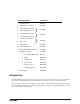
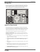
Included Equipment Part Number 1. Viewing Screen OS-8460 2. Adjustable Lens Holder OS-8474 3. +100 mm Mounted Lens 4. +200 mm Mounted Lens OS-8456 5. +250 mm Mounted Lens 6. −150 mm Mounted Lens OS-8519 7. Concave/convex Mirror OS-8457 8. Half-screen 9. Light Source OS-8470 10. 1.2 m Optics Bench OS-8508 11. Ray Table with D-shaped Lens OS-8465 12. Ray Optics Kit with: OS-8516A a. Storage Box/Water Tank 740-177 b. Mirror 636-05100 c. Hollow Lens OS-8511 d. Convex Lens 636-05501 e.
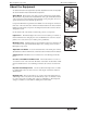
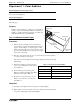
Basic Optics System About the Equipment About the Equipment For detailed information on the Light Source, Ray Table, Adjustable Lens Holder, and Ray Optics Kit, see the instruction sheets included with those components. Optics Bench Basic Optics components, such as mounted lenses and the adjustable lens holder, snap into the wide central channel of the optics bench. Place the base of the component on the bench and push down firmly to snap it in place.
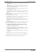
Model No. OS-8515C Storage Box Storage Box Use the foam-padded box to store, organize, and protect the system’s components. Place the components in the fitted compartments as illustrated below. Extra compartments are included for additional components as spare parts. A full-page diagram appears on page 69. Remove or copy that page and attach it the box lid.
Basic Optics System About the Experiments 6. Convex and Concave Lenses (page 19): Use ray tracing to determine the focal lengths of lenses. 7. Hollow Lens (page 21): Use the hollow lens and water to explore how the properties of a lens are related to its shape, its index of refraction, and the index of refraction of the surrounding medium. 8. Lensmaker’s Equation (page 23): Determine the focal length of a concave lens by measuring its radius of curvature. 9.
Model No. OS-8515C E x p e r i m e n t 1 : C o l o r A d d it i o n Experiment 1: Color Addition Required Equipment from Basic Optics System Light Source Convex Lens from Ray Optics Kit Other Required Equipment Red, blue, and black pens Blank white paper Purpose Light source In Part 1 of this experiment, you will discover the results of mixing red, green, and blue light in different combinations. In Part 2, you will compare the appearance of red, blue, and black ink illuminated by red and blue light.
Basic Optics System E x p e r i m e n t 1 : C o l o r A d d it i o n Part 2: Observing Colored Ink Under Colored Light Procedure 1. While you look away, have your partner draw two lines—one red and one black—on a sheet of white paper. One of the lines should be labeled A, and the other B, but you should not know which is which. Before you look at the paper, have your partner turn off the room lights and cover the red and green bars so the paper is illuminated only with blue light. Now look.
Model No. OS-8515C Experiment 2: Prism Experiment 2: Prism Required Equipment from Basic Optics System Light Source Trapezoid from Ray Optics Kit Blank white paper Purpose Incident ray The purpose of this experiment is to show how a prism separates white light into its component colors and to show that different colors are refracted at different angles through a prism.
B a s ic O p t i c s S y s t e m 3. Experiment 2: Prism Rotate the trapezoid until the angle (θ) of the emerging ray is as large as possible and the ray separates into colors. (a) What colors do you see? In what order are they? (b) Which color is refracted at the largest angle? (c) According to Snell’s Law and the information given about the frequency dependence of the index of refraction for acrylic, which color is predicted to refract at the largest angle? 4.
Model No. OS-8515C Experiment 3: Reflection Experiment 3: Reflection Required Equipment from Basic Optics System Light Source Mirror from Ray Optics Kit Other Required Equipment Drawing compass Protractor Metric ruler White paper Purpose In this experiment, you will study how rays are reflected from different types of mirrors. You will measure the focal length and determine the radius of curvature of a concave mirror and a convex mirror. Part 1: Plane Mirror Procedure 1.
B a s ic O p t i c s S y s t e m Experiment 3: Reflection the incoming and the outgoing rays and mark them with arrows in the appropriate directions. Questions 1. What is the relationship between the angles of incidence and reflection? 2. Are the three colored rays reversed left-to-right by the plane mirror? Part 2: Cylindrical Mirrors Theory mirror R A concave cylindrical mirror focuses incoming parallel rays at its focal point.
Model No. OS-8515C Experiment 4: Snell’s Law Experiment 4: Snell’s Law Required Equipment from Basic Optics System Light Source Trapezoid from Ray Optics Kit Other Required Equipment Protractor White paper Purpose The purpose of this experiment is to determine the index of refraction of the acrylic trapezoid. For rays entering the trapezoid, you will measure the angles of incidence and refraction and use Snell’s Law to calculate the index of refraction.
Basic Optics System 7. E x p e r i m e n t 4 : S n e ll ’ s L a w On a new sheet of paper, repeat steps 2–6 with a different angle of incidence. Repeat these steps again with a third angle of incidence. The first two columns of Table 4.1 should now be filled. Table 4.1: Data and Results Angle of Incidence Angle of Refraction Calculated index of refraction of acrylic Average: Analysis 1. For each row of Table 4.
Model No. OS-8515C E xp e r i m e n t 5 : T o t a l I n t e r n a l R e f l e c t i o n Experiment 5: Total Internal Reflection Required Equipment from Basic Optics System Light Source Trapezoid from Ray Optics Kit Other Required Equipment Protractor White paper Purpose In this experiment, you will determine the critical angle at which total internal reflection occurs in the acrylic trapezoid and confirm your result using Snell’s Law.
Basic Optics System Experiment 5: Total Internal Reflection Procedure 1. Place the light source in ray-box mode on a sheet of white paper. Turn the wheel to select a single ray. 2. Position the trapezoid as shown in Figure 5.3, with the ray entering the trapezoid at least 2 cm from the tip. 3. Rotate the trapezoid until the emerging ray just barely disappears. Just as it disappears, the ray separates into colors. The trapezoid is correctly positioned if the red has just disappeared. 4.
Model No. OS-8515C Experiment 6: Convex and Concave Lenses Experiment 6: Convex and Concave Lenses Required Equipment from Basic Optics System Light Source Convex Lens from Ray Optics Kit Concave Lens from Ray Optics Kit Other Required Equipment Metric ruler Purpose In this experiment, you will explore the difference between convex and concave lenses and determine their focal lengths. Theory When parallel light rays pass through a thin lens, they emerge either converging or diverging.
Basic Optics System 20 E x p e r i m e n t 6 : C o n v e x a n d C o n c a ve L e n s e s 5. Nest the convex and concave lenses together and place them in the path of the parallel rays (see Figure 6.2). Trace the rays. Are the outgoing rays converging, diverging or parallel? What does this tell you about the relationship between the focal lengths of these two lenses? 6. Slide the convex and concave lenses apart by a few centimeters and observe the effect. Then reverse the order of the lenses.
Model No.
Basic Optics System Experiment 7: Hollow Lens Repeat this step with water in different section of the lens to complete the first four rows of Table 7.1. Table 7.1: Predictions and Observations Lens surrounded by: Section 1 filled with: Section 2 filled with: Section 3 filled with: Water Air Air Air Water Air Air Air Water Water Air Water Air Water Water Water Air Water Water Water Air Prediction (converging or diverging) Observation (converging or diverging) Air Water 4.
Model No. OS-8515C Experiment 8: Lensmaker’s Equation Experiment 8: Lensmaker’s Equation Required Equipment from Basic Optics System Light Source Concave Lens from Ray Optics Kit Other Required Equipment Metric ruler Purpose In this experiment you will determine the focal length of a concave lens in two ways: a) by direct measurement using ray tracing and b) by measuring the radius of curvature and using the lensmaker’s equation.
Basic Optics System Experiment 8: Lensmaker’s Equation 2. Trace around the surface of the lens and trace the incident and transmitted rays. Indicate the incoming and the outgoing rays with arrows in the appropriate directions. 3. Remove the lens. To measure the focal length, use a ruler to extend the outgoing diverging rays straight back through the lens. The focal point is where these extended rays cross. Measure the distance from the center of the lens to the focal point.
Model No. OS-8515C Experiment 9: Apparent Depth Experiment 9: Apparent Depth Required Equipment from Basic Optics System Light Source Trapezoid from Ray Optics Kit Convex Lens from Ray Optics Kit Mirror from Ray Optics Kit (used to block rays) Other Required Equipment Metric ruler White paper Very sharp pencil Purpose In this experiment, you will use two different methods to measure the apparent depth of the acrylic trapezoid.
Basic Optics System Experiment 9: Apparent Depth Trapezoid Figure 9.2 2. With both eyes, look down through the top of the trapezoid. Does the line viewed through the trapezoid appear to be closer? Close or cover one eye, and move your head side to side. Do you see parallax between the line viewed through the trapezoid and the line viewed directly? 3. In this step, you will hold a pencil near the trapezoid to determine the position of the apparent line.
Model No. OS-8515C Experiment 9: Apparent Depth 2. Mark the place on the paper where the two rays cross each other. 3. Position the trapezoid as shown in Figure 9.4. The “bottom” surface of the trapezoid must be exactly at the point where the two rays cross. The crossed rays simulate rays that originate at an object on the “bottom” of the block. 4. Trace the trapezoid and trace the rays diverging from the “top” surface. 5. Remove the trapezoid and light source.
Basic Optics System 28 Experiment 9: Apparent Depth ®
Model No. OS-8515C E x p e r i m e n t 1 0 : R e v e r s i b i l i ty Experiment 10: Reversibility Required Equipment from Basic Optics System Ray Table D-shaped Lens Light Source Purpose In Trial 1 of this experiment, you will determine the relationship between the angle of incidence and the angle of refraction for light passing from air into a more optically dense medium (the acrylic of the D-shaped lens).
Basic Optics System E x p e r i m e n t 1 0 : R e v e r s i b i l i ty Record Data Table 10.1: Data Trial 1 Ray Incident on Flat Surface Trial 1 1. 2. Turn the ray table so the incoming ray enters the lens through the flat surface (see Figure 10.2).
Model No. OS-8515C Experiment 11: Dispersion Experiment 11: Dispersion Required Equipment from Basic Optics System Ray Table D-shaped Lens Light Source Purpose The purpose of this experiment is to determine the index of refraction of acrylic at two different wavelengths. Theory When light crosses the boundary between two transparent media, it is refracted.
Basic Optics System Experiment 11: Dispersion the ray enters the lens through the curved surface, and the angle of incidence is 0°. Procedure 1. Hold a piece of white paper vertically near the edge of the Ray Table so the outgoing ray is visible on the paper. 2. Slowly rotate the ray table to increase the angle of incidence. Notice that the ray is refracted only at the flat surface of the lens, not at the curved surface.
Model No. OS-8515C Experiment 12: Focal Length and Magnification of a Thin Lens Experiment 12: Focal Length and Magnification of a Thin Lens Required Equipment from Basic Optics System Light Source Bench Converging lens of unknown focal length1 Screen Other Equipment Metric ruler Optics Caliper (optional, for measuring image sizes), PASCO part OS-8468 1Instructors: see note on page 63.
Basic Optics System 2. Experiment 12: Focal Length and Magnification of a Thin Lens Use the Thin Lens Formula (Equation 12.1) to calculate the focal length. f = _______________ Part II: Object Closer Than Infinity In this part, you will determine the focal length by measuring several pairs of object and image distances and plotting 1/d o versus 1/d i. 1m Screen Light source Lens Figure 12.1 Procedure 1.
Model No. OS-8515C Experiment 12: Focal Length and Magnification of a Thin Lens Table 12.1: Image and Object Distances Distance from light source to screen do di 1/d o 1/d i Image Size Object Size 100 cm 90 cm 80 cm 70 cm 60 cm 50 cm 3. For each intercept, calculate a value of f and record it in Table 12.2. 4. Find the percent difference between these two values of f and record them in Table 12.2. 5. Average these two values of f.
Basic Optics System 2. Calculate the absolute value of M (for each of the two lens positions) using your measurements of the image size and object size. Record the results in Table 12.3. image size M = ------------------------object size (eq. 12.3) 3. Experiment 12: Focal Length and Magnification of a Thin Lens Calculate the percent differences between the absolute values of M found using the two methods. Record the results in Table 12.3. Table 12.
Model No.
B a s ic O p t i c s S y s t e m 2. Experiment 13: Focal Length and Magnification of a Concave Mirror Use the Equation 13.1 to calculate the focal length. f = _______________ Part II: Object Closer Than Infinity In this part, you will determine the focal length of the mirror by measuring several pairs of object and image distances and plotting 1/d o versus 1/d i. 50cm Light source Half-screen Mirror Figure 13.2 Procedure 1.
Model No. OS-8515C Experiment 13: Focal Length and Magnification of a Concave Mirror Analysis Part A: Focal Length 1. Calculate 1/d o and 1/d i for all six rows in Table 13.1. 2. Plot 1/d o versus 1/d i and find the best-fit line (linear fit). This will give a straight line with the x- and y-intercepts equal to 1/f.
B a s ic O p t i c s S y s t e m 3. Experiment 13: Focal Length and Magnification of a Concave Mirror Calculate the percent differences between the absolute values of M found using the two methods. Record the results in Table 13.3. Table 13.3: Magnification M calculated from image and object distances M calculated from image and object sizes % difference Questions 40 1. Is the image formed by the mirror upright or inverted? 2. Is the image real or virtual? How do you know? 3.
Model No. OS-8515C Experiment 14: Virtual Images Experiment 14: Virtual Images Required Equipment from Basic Optics System Light Source Bench -150 mm lens +200 mm lens Viewing screen Concave/convex Mirror Half-screen Other Equipment Tape Purpose In this experiment, you will study virtual images formed by a diverging lens and a convex mirror. Theory A virtual image cannot be viewed on a screen. It forms where the backwards extensions of diverging rays cross.
Basic Optics System 4. Experiment 14: Virtual Images Look through the lens toward the light source (see Figure 14.1). Describe the image. Is it upright or inverted? Does it appear to be larger or smaller than the object? ________________________________________________________________ ________________________________________________________________ ________________________________________________________________ 5.
Model No. OS-8515C Experiment 14: Virtual Images Analysis The current position of the light source is identical to the previous position of the virtual image. 1. Calculate the virtual image distance d i1 (the distance between the negative lens and the virtual image). Remember that it is a negative. Record it in Table 14.1. 2. Calculate the magnification and record it in Table 14.1. ⎛ d i1 ⎞ M 1 = – ⎜ --------⎟ ⎝ d o1⎠ (eq. 14.1) Table 14.1: Negative Lens d o1 d i1 M1 Questions 1.
Basic Optics System 4. Experiment 14: Virtual Images Look through the half-screen into the mirror. Describe the image of the half-screen. Is it upright or inverted? Does it appear to be larger or smaller than the object? ________________________________________________________________ ________________________________________________________________ ________________________________________________________________ 5. Mirror Viewing screen Halfscreen Guess where the image is.
Model No. OS-8515C 3. Experiment 14: Virtual Images Use d o and d i to calculate the magnification and record it in Table 14.1. Table 14.2: Convex Mirror do di M Questions 1. Is the magnitude of d i less than or greater than d o? If you replace the convex mirror with a plane mirror, what would be the relationship between d i and d o? 2. Is M positive or negative? How does this relate to the appearance of the image? 3.
Basic Optics System 46 Experiment 14: Virtual Images ®
Model No. OS-8515C Experiment 15: Telescope Experiment 15: Telescope Required Equipment from Basic Optics System Bench 2 Convex Lenses (+100 mm and +200 mm) Screen Paper grid pattern (see page 57), or a 14 × 16 grid of 1 cm squares +250 mm and -150 mm lenses (optional, for further study) Purpose In this experiment, you will construct a telescope and determine its magnification. Theory -di2 do1 di1 do2 Object Image Eye Lens +200 mm Lens +100 mm Figure 15.
Basic Optics System Experiment 15: Telescope end of the optics bench and place the screen on the other end (see Figure 15.2). Their exact positions do not matter yet. +200 mm objective lens +100 mm eyepiece lens Screen Figure 15.2 Procedure 1. Put your eye close to the eyepiece lens and look through both lenses at the grid pattern on the screen. Move the objective lens to bring the image into focus. Objective Eyepiece lens lens Screen Right eye Left eye Figure 15.3 2.
Model No. OS-8515C 1. Experiment 15: Telescope Measure d o1, the distance from the object (paper pattern on screen) to the objective lens. Table 15.1: Results Position of Objective Lens 2. Determine d i2, the distance from the eyepiece lens to the image. Since the image is in the plane of the object, this is equal to the distance between the eyepiece lens and the object (screen). Remember that the image distance for a virtual image is negative.
Basic Optics System 50 Experiment 15: Telescope ®
Model No. OS-8515C E x p e r i m e n t 1 6 : M ic r o s c o p e Experiment 16: Microscope Required Equipment from Basic Optics System Bench 2 Convex Lenses (+100 mm and +200 mm) Screen Paper grid pattern (see page 57), or a 14 × 16 grid of 1 cm squares Purpose In this experiment, you will construct a microscope and determine its magnification. Theory di2 do1 di1 do2 Object Image Eye Lens +100 mm Lens +200 mm Figure 16.1 A microscope magnifies an object that is close to the objective lens.
B a s ic O p t i c s S y s t e m E x p e r im e n t 1 6 : M ic r o s c o p e middle of the optics bench and place the screen near the end of the bench (see Figure 16.2). +100 mm objective lens +200 mm eyepiece lens Screen Figure 16.2 Procedure 1. Put your eye close to the eyepiece lens and look through both lenses at the grid pattern on the screen. Move the objective lens to bring the image into focus. Objective Eyepiece lens lens Screen Right eye Left eye Figure 16.3 2.
Model No. OS-8515C E x p e r i m e n t 1 6 : M ic r o s c o p e Analysis To calculate the magnification complete the following steps and record the answers in Table 16.1: 1. Measure d o1, the distance from the object (paper pattern on screen) to the objective lens. 2. Determine d i2, the distance from the eyepiece lens to the image. Since the image is in the plane of the object, this is equal to the distance between the eyepiece lens and the object (screen).
B a s ic O p t i c s S y s t e m 54 E x p e r im e n t 1 6 : M ic r o s c o p e ®
Model No. OS-8515C Experiment 17: Shadows Experiment 17: Shadows Required Equipment from Basic Optics System (2 systems needed) 2 Benches 2 Light Sources 1 Screen Purpose The purpose of this experiment is to show the umbra (darker part) and the penumbra (lighter part) of the shadow. Set Up 1. Place the two optics benches beside each other. 2. Put one light source on each bench with the point source (circular hole) facing the other end of the bench. 3.
B a s ic O p t i c s S y s t e m 56 E xp e r i m e n t 1 7 : S h a d o ws ®
Model No. OS-8515C Telescope and Microscope Test Pattern Telescope and Microscope Test Pattern Attach a copy of this pattern to the viewing screen for experiments 15 and 16.
B a s ic O p t i c s S y s t e m 58 Telescope and Microscope Test Pattern ®
Model No. OS-8515C Teacher’s Guide Teacher’s Guide Experiment 1: Color Addition Note on procedure: Student’s expectation may differ from actual results. Encourage them to carefully observe the resulting colors and describe them accurately. Part 1, typical results: Table 1.1: Results of Colored Light Addition Colors Added Resulting Color red + blue + green slightly bluish-white red + blue pink-purple red + green yellow-orange green + blue bluish-green Part 1, answers to questions: 1.
B a s ic O p t i c s S y s t e m T e a c h e r ’s G u i d e Experiment 3: Reflection Part 1, typical results: Table 3.1: Plane Mirror Results Angle of Incidence Angle of Reflection 9.0° 9.2° 16.8° 16.5° 19.0° 37.8° Part 1, answers to questions: 1. The angle of incidence and the angle of reflection are equal. 2. The three colored rays are not reversed by the mirror. Part 2, typical results: Table 3.2: Cylindrical Mirror Results Concave Mirror Convex Mirror Focal Length 6.2 cm 6.
Model No. OS-8515C Teacher’s Guide Experiment 6: Convex and Concave Lenses Typical results: Table 6.1: Results Focal Length Convex Lens Concave Lens 13.75 cm -12.1 cm (Step 5) When the lenses are nested together, parallel rays entering the lenses emerge nearly parallel; this tells us that the focal lengths are of approximately equal magnitude and opposite sign. (Step 6) By moving the lenses apart, the spacing of the rays can be changed, but they remain nearly parallel.
B a s ic O p t i c s S y s t e m T e a c h e r ’s G u i d e Experiment 9: Apparent Depth Typical results: Table 1.1: Results d t n Part 1: Parallax method 2.12 cm 3.18 cm 1.50 Part 2: Ray-tracing method 2.23 cm 3.18 cm 1.43 Typical ray-tracing results are represented at 50% scale in Figure TG.1. The gray regions represent the actual light beams; the black lines and dots represent the student’s actual marks. Notice that this student traced along the edges of the light beams. 2.
Model No. OS-8515C Notes on analysis: 1. 2. One way to find n acrylic is to plot sin(θi1) versus sin(θr1) and find the best-fit line. The slope of the line is equal to 1/n acrylic. Using this method and the data above, n acrylic= 1.498 for Trial 1. For Trial 2, n acrylic is the slope of sin(θi2) versus sin(θr2), thus n acrylic= 1.50. Teacher’s Guide 1.0 Trial 2 slope = 1.498 ± 0.009 0.8 0.6 0.4 0.2 Trial 1 slope = 0.666 ± 0.013 1/slope = 1.50 ± 0.03 0.0 0.0 0.2 0.4 0.6 0.8 1.
B a s ic O p t i c s S y s t e m T e a c h e r ’s G u i d e Part 2, typical results: Table 12.1: Image and Object Distances Distance from light source to screen do 1/d o di 1/d i -1) (cm-1) Image Size Object Size (cm) (cm) (cm 88.5 11.5 0.0113 0.0870 5.5 mm 42 mm 11.0 89.0 0.0909 0.0112 81 mm 10 mm 78.3 11.7 0.0128 0.0855 11.3 78.7 0.0885 0.0127 68.0 12.0 0.0147 0.0833 11.5 68.5 0.0870 0.0146 57.7 12.3 0.0173 0.0813 11.9 58.1 0.0840 0.0172 47.1 12.9 0.
Model No. OS-8515C Teacher’s Guide Experiment 13: Focal Length and Magnification of a Concave Mirror Part 1: For a distant object, 1/d o approaches zero, therefore the image will form clearly with a mirror-to-screen distance of d i = f ≅ 10 cm. Part 2, typical results: Table 13.1: Image and Object Distances do di (cm) 1/d o (cm-1) 1/d i (cm-1) 50.0 cm 12.5 0.0200 0.0800 45.0 cm 12.9 0.0222 0.0775 40.0 cm 13.4 0.0250 0.0743 35.0 cm 14.0 0.0286 0.0714 30.0 cm 14.85 0.0333 0.0673 25.
B a s ic O p t i c s S y s t e m T e a c h e r ’s G u i d e Experiment 14: Virtual Images Part 1, notes on procedure: (Step 4) The image is upright and appears smaller than the object. (Step 5) Answers will vary. By observing parallax between the image and the light source, you can determine that the image is in front of the object. (Step 8) When the negative lens is removed, the image on the screen goes “out of focus.” Part 1, typical results: Table 14.1: Negative Lens d o1 20.0 cm d i1 -8.
Model No. OS-8515C Teacher’s Guide Experiment 15: Telescope Typical results: Table 15.1: Results Answers to questions: Position of Objective Lens 63.4 cm Position of Eyepiece Lens 102.2 cm Position of Screen 0.0 cm Observed magnification -5 d o1 63.4 cm d i2 -102.2 cm d i1 29.2 cm d o2 9.6 cm Calculated Magnification -4.9 Percent Difference 2% 1. The image is inverted. 2. It is a virtual image.
B a s ic O p t i c s S y s t e m T e a c h e r ’s G u i d e Further study, Image Formed by the Objective Lens: The objective lens forms a real, upright image; to see it, hold a sheet of paper at distance d i1 from the objective. When a pencil is placed at this location, it’s virtual image, viewed through the eyepiece lens, coincides with the virtual image of the grid pattern viewed through both lenses.
Model No.
B a s ic O p t i c s S y s t e m 70 Storage Box ®
Model No. OS-8515C Technical Support Technical Support For assistance with any PASCO product, contact PASCO at: Address: PASCO scientific 10101 Foothills Blvd. Roseville, CA 95747-7100 Phone: 916-786-3800 (worldwide) 800-772-8700 (U.S.) Fax: (916) 786-7565 Web: www.pasco.com Email: support@pasco.com Limited Warranty For a description of the product warranty, see the PASCO catalog.