Instruction Manual for the PASCO scientific Model OS-8535 012-06551A 1/98 LINEAR TRANSLATOR FOR THE BASIC OPTICS SYSTEM © 1998 PASCO scientific $10.
012-06551A Basic Optics Linear Translator Table of Contents Section Page Copyright, Warranty, and Equipment Return ..................................................... ii Description ....................................................................................................... 1 Mounting the Translator on the Optics Bench .................................................... 1 Using a Rotary Motion Sensor ..........................................................................
Basic Optics Linear Translator 012-06551A Copyright, Warranty and Equipment Return Please—Feel free to duplicate this manual subject to the copyright restrictions below. Copyright Notice Equipment Return The PASCO scientific Model OS-8535 Linear Translator manual is copyrighted and all rights reserved.
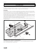
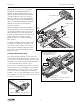
012-06551A Basic Optics Linear Translator Introduction The PASCO OS-8535 Linear Translator is designed to be mounted on the Optics Bench of the OS-8515 Basic Optics System. The Linear Translator can also be mounted on a rod up to 0.5 inch (12 mm) diameter. Description The Linear Translator consists of a base with mounting hardware and an attached rod clamp, a rack, and a rack clamp. The hole in the base allows it to be stored on a peg.
Basic Optics Linear Translator 012-06551A Pependicular Mount To mount the Linear Translator so the Rack is perpendicular, leave the mounting hardware (thumbscrew and square nut) in the center hole. Loosen the thumbscrew by turning the thumbscrew counter-clockwise while holding the square nut. Leave the square nut on the end of the thumbscrew. Attach the base to the Optics Bench by inserting the square nut into the T-slot located along the center of the Optics Bench.
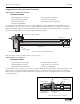
012-06551A Basic Optics Linear Translator When the Rack is in the T-slot, put the Rack Clamp back onto the Rack and tighten its thumbscrew. Place the Rack with the sensor back onto the Linear Translator. The back end of the Rotary Motion Sensor rests on the upright edge of the base of the Linear Translator. Line up the holes in the ends of the Rack with the holes on the Linear Translator base. Put the thumbscrews into the holes and turn them clockwise to tighten.
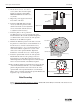
Basic Optics Linear Translator 012-06551A Suggestions for Using the Linear Translator Light Intensity of Diffraction Patterns EQUIPMENT NEEDED – Optics Bench (part of OS-8515) – Aperture Bracket (OS-8534) – Diode Laser (OS-8525) – Light Sensor (CI-6504A) – Linear Translator (OS-8535) – Slit Accessory (OS-8523) – Rotary Motion Sensor (CI-6538) Use the Diode Laser and Slit Accessory to produce a diffraction pattern.
012-06551A Basic Optics Linear Translator Set Up for a Diffraction Pattern Experiment EQUIPMENT NEEDED – Optics Bench (part of OS-8515) – Aperture Bracket (OS-8534) – Diode Laser (OS-8525) – Light Sensor (CI-6504A) – Linear Translator (OS-8535) – Slit Accessory (OS-8523) – Rotary Motion Sensor (CI-6538) Introduction The purpose is to investigate the wave nature of light.
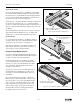
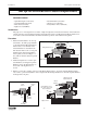
Basic Optics Linear Translator 012-06551A 4. Mount the Diode Laser and a Slit Accessory at the other end of the Optics Bench. For example, put the MULTIPLE SLIT SET into the Slit Accessory holder. Slit Accessory 5. Plug in the power supply for the Diode Laser. Turn on the laser. thumbscrew Optics Bench Figure 4 TS LI ES 0 0. . 08 25 BL SET a= 0.04 0.04 0.25 d= 865 646-05 25 PA R IS ON d= 4 0. 1 MU L TIP S CO M 5 a= 0.0 4 0.0 d= 0.2 5 0.5 4 S 0 PTIC RY a = IC O O d = 0.0 BAS CCESS 0.
012-06551A Basic Optics Linear Translator Technical Support Feedback Contacting Technical Support If you have any comments about the product or manual, please let us know. If you have any suggestions on alternate experiments or find a problem in the manual, please tell us. PASCO appreciates all customer feedback. Your input helps us evaluate and improve our product.