
User manual


9
INT-30A Owners Manual
So the amplifier is sitting there unconnected.
Make sure that the rear panel power switch is off (down). Plug the AC
cord into the back of the amplifier, and then into the wall. Then turn the
power switch on (up). The lights in your house may dim for a moment as
the power supply charges the capacitors.
Please note that this switch is not a “safety device” or “emergency
disconnect” for this product. This switch does not provide personal
shock protection in the manner of a ground-fault interrupter, nor is it
intended to. One more reason why it is important not to defeat the Earth
connection of your power cord. Safety or Emergency disconnect involves
removing a power cord, we feel that this is the most positive and safest
solution.
On the front panel, the “power” LED indicator should be glowing blue,
indicating that AC power is available and the capacitor banks are charged.
If the “LED” is not glowing blue, then cycle the front panel power button
to “on” and turn the volume control just to verify operation.
Now turn off the front and rear power switches and unplug the AC power
cord from the wall while you connect the speakers and inputs. Amplifier
output terminals and speaker terminals will be electrically live when the
amplifier is on.
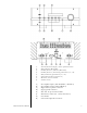
Check to make certain that the loudspeaker cables aren’t shorted at the
loudspeaker end, and then connect speaker cables to the output binding
posts on the amplifiers, observing correct polarity. The output binding
posts will accept either bare wire or spades. (Regulatory agencies in many
countries have banned binding posts that will accept a banana plug, forcing
us to abandon this option.) Make sure that your speaker wires only attach
to the outputs of the amplifier, not to each other and never to the amplifier
case.
Remember the warning about treating the output connections as ground,
particularly if you are using a powered subwoofer with this amplifier. If
you need a ground, use the one provided specifically on the rear panel of
the amplifier.
The amplifier may be driven single-end or balanced, your choice. Single-
ended input will always occur through the RCA connector and balanced
input will always occur through the XLR connector.
Again, if you drive the amplifier single-ended then leave the supplied
jumpers in place between pins 1 & 3 on the input XLR.
On the XLR connector pin 1 is ground, pin two is positive input and pin 3
is inverted (negative) input. Pin numbers are marked on the XLR. If you
re-install the jumper incorrectly or leave it lying about, the amplifier will not
work properly, and you will be able to tell.