Pass Laboratories Owner's Manual X1000 / X600 / X350 Page 1
Now For Something Completely Different: The X Series are the biggest and most powerful amplifiers we have created, but they are not unique for that reason. We have chosen the biggest and most powerful as the proper temple for a new concept in high performance audio amplification. Called Supersymmetry™, the circuit topology was granted a U.S. patent in 1994, and is the result of 19 years of effort by Pass. The amplifier uses highly matched components in a classically simple balanced Class A circuit.
Setup First off, let’s be clear about one thing. These amplifiers are very heavy. In the case of an X1000, we strongly suggest that you get four, not two, people to help you lift it. Yeah, maybe two people could do it, but if you get hurt, don’t say you weren’t warned. X600 and X350 models are not much lighter, either. Make the dealer lift it. You can position the amplifier anywhere you want, but it requires ventilation.
the front panel stand-by button to go to stand-by mode, with the meter light off and the meter parked to the left. OK, so the amplifier is sitting there in stand-by mode with just the single blue led lit. No speaker connected yet. You can go ahead and connect the source now. The amplifier requires a fully balanced source, that is to say a male XLR connector with pin 1 at ground, pin 2 positive signal, and pin 3 negative signal.
of our amplifiers is almost non-existent. This is small comfort to the few, but take it easy and give us a call if you have problems. Now that the channels are up and running, we can take a moment to note a few things. The meter lights are blue, subtle lighting in daylight, a little more dramatic at night. The meters themselves read the amount of current going through the amplifier, and that is why they sit near the half-way point, reflecting the bias current we run through them to get low distortion.
9 volts to 15 volts. This switching is independent of the front panel button, so if the amplifier is placed in operating mode by the button, the relay will not turn it off, only on. So much for essential information. Speaker Interface The X Series is optimized for loads nominally rated at 4 ohms and above. You can run the amplifiers into a lower nominal impedance without difficulty, and we are not aware of a speaker on the market that presents unusual difficulty with these amplifiers.
and the energy reserve held in the capacitors will do its job. As a practical matter, it will not make a lot of difference. Just don’t call us up and complain that you only measured 1900 watts in your living room. If you do, we’ll want to know what speakers can take it. Interconnects and Speaker Cables We have a general recommendation about interconnects, which is that they should cost less than the amplifier.
Fun Hardware Facts The X1000 has two power transformers, rated at 1500 watts each, continuous duty at 85 degrees centigrade. Under actual conditions in the amplifier, they will do about 2000 watts continuously each, and at least half again more than that for short durations. The X600 and X350 have one of these transformers in each chassis. To avoid huge inrush of current during charge up, each of the two transformer primary coils has its own inrush suppressor, which keeps the inrush down to 100 amps or so.
boards in the amplifier are double sided, with plated through holes and double thickness of copper. So how long will this hardware last? It is my experience that, barring abuse or the odd failure of a component, the first things to go will be the power supply capacitors, and from experience, they will last 15 to 20 years. Fortunately they die gracefully and are easily replaced.
Supersymmetry: What it is, Where it came from, How it works, Why bother ( theory and philosophy you can skip ) Supersymmetry is the name given to a new type of amplifying circuit, which operates quite differently than the designs presently appearing in literature and the marketplace. I have been designing new amplifiers all my adult life, and patented eight of them, but I regard this particular idea as the most interesting and profound.
nature of the device. So I will state here and now that I consider “no feedback” to be where feedback does not extend further than a single gain device or stage, so that circuits having “local feedback” are still considered “no feedback”. Anybody disagreeing with this should send me a diagram of a “true no feedback” circuit, and I will try to point out the hidden feedback.
sink in it. Now I strive to be like Picasso, who could draw a woman with a single pencil stroke and create a masterpiece. Supersymmetry is not a single pencil stroke, but I am making progress. Its origin goes back to the late 1970’s when I was examining the virtues and faults of so-called “error correcting amplifiers”, an alternative to conventional feedback. In this approach, two amplifiers, a big one and a small one work together.
feedback with a Supersymmetric connection another 20 dB or so. This is easily accomplished with only one gain stage instead of the multiple stages required by conventional design, and so it results in only one “pole” of high frequency characteristic, and is unconditionally stable without compensation. In fact, if you build a supersymmetric circuit with multiple gain stages, it does not work as well. In 1993 I attempted to build the first power amplifier using this principle, but it was not successful.
People inevitably will ask how this relates to bridged amplifiers in general, and the balanced amplifier offerings of other companies. It is similar only in that both terminals of the output to the speaker are “live”; neither of them is grounded. You could in fact “bridge” two X1000’s together to give you an 8 kilowatt peak into 8 ohms.
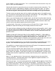
On this curve (B) we can clearly see that intrinsic symmetry due to the matching of the two halves reduces the distortion by a factor of 10. Supersymmetry (D) creates a more perfect match, and results in an additional reduction by a factor of 10. However there is essentially no difference in the distortion figures at the output (C) of each half of the circuit considered alone.
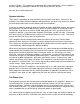
X1000 CURVES Page 16
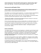
X600 CURVES Page 17
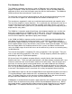
X350 CURVES Page 18
X1000 SPECIFICATIONS All figures obtained after 1 hour warmup, with regulated 120 VAC power line. See manual notes about AC power line regulation. Gain 30 dB Freq.
X600 SPECIFICATIONS All figures obtained after 1 hour warmup, with regulated 120 VAC power line. See manual notes about AC power line regulation. Gain 30 dB Freq.
X350 SPECIFICATIONS All figures obtained after 1 hour warmup, with regulated 120 VAC power line. See manual notes about AC power line regulation. Gain 26 dB Freq.