
Owner manual

Model 1009 • DMX/RDM Splitter Manual
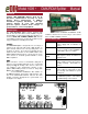
STATUS INDICATORS
CONNECTIONS
POWER IN
Blue. Glowing steadily indicates
power supply OK; off indicates no
power.
PROCESSOR
Green. Glowing steadily indicates
processor is OK; off when POWER IN
is lit indicates processor failure.
DMX
INPUT
Amber. Glowing steadily indicates
data signal received; off indicates no
signal present.
ISO POWER IN
Red. Indicates the internally isolated
power supply for input processing is
working correctly. Off indicates no
power.
ISO POWER
A/B/C/D
Red. Indicates internally isolated
power supply for output ports is work-
ing correctly. Off indicates no power
to that port.
RDM A/B/C/D
Amber. Flickering indicates presence
of RDM data packets. Off indicates
no RDM activity on the network.
OVERVIEW
Pathway eDIN DMX/RDM Splitters allow the bi-
directional communications necessary for E1.20
Remote Device Management in DMX512
installations requiring star-wiring. Full opto-
isolation between all ports adds maximum
protection against common mode voltages or
ground faults for connected equipment.
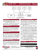
The eDIN DMX/RDM Splitter features terminal strips
that can be removed from the card to facilitate easy wir-
ing installation or replacement. Make the following con-
nections, WITH THE POWER TURNED OFF, and ob-
serve ESD precautions by ensuring the installer is prop-
erly grounded before handling the module.
POWER
The DMX/RDM Splitter is designed to run on a range of
voltages from 9-30 volts DC. Each eDIN module re-
quires 6 watts. Observe the correct polarity when con-
necting to V+ and V-. A second set of terminals are pro-
vided as a thru connection to other eDIN modules. The
EARTH GND terminal must be connected to the enclo-
sure’s chassis or electrical ground terminal to ensure
EMC compliance.
DMX
DMX connections consist of a shield and a data pair. A
optional second auxiliary data pair is also occasionally
employed. DMX IN usually comes from a control con-
sole, Pathport
®
node, architectural controller or opto-
splitter. DMX THRU provides a means to daisy-chain
DMX to other eDIN modules.
Connect DATA+ and DATA- to D1+ and D1– on
the DMX IN terminal. Connect the cable shield or com-
mon to the SHLD COM terminal. Observe the same
polarity convention throughout the system while con-
necting the four outputs.
ISO INPUT PWR
Rev.1 0824
4 - PORT DMX/RDM SPLITTER
ENABLE
DISABLE
RDM
RDM A RDM B RDM C RDM D
ISO PWR A ISO PWR B ISO PWR C ISO PWR D
POWER
PROCESSOR
DMX/RDM
Connect wires for DATA2+ and DATA2– to D2+
and D2–, if desired. It is not necessary to connect these
wires for DMX or RDM to function.