
Configuration


DMXPowerPanel Installation & Configuration
INSTALLATION CONTINUED
2
INSIDE THE POWERLINK PANEL
• Locate the Power Interface Module inside the POWERLINK panel. On the left side there is a plastic cover la-
beled TERMINAL COVER. Embossed on the cover are instructions for its removal using a slot screwdriver.
Remove the cover. Inside there are a number of terminals. Locate the terminals labeled EXP. Connect the data
cable leading from the terminal strip marked “POWERLINK” inside the Interface Module, to the EXP terminals.
Use the table below to ensure your connections are correct.
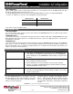
Interface Module terminals POWERLINK EXP terminals
GND SH
TXD RX
RXD TX
• Connect one of the pigtails from the transformer installed in the Interface Module to a standard breaker
(not controllable). Connect the other pigtail to the neutral bar.
• Connect the output of the supplied transformer to the PWR SUPPLY (V+ and COM) terminals using the wires
supplied. These wires can be reversed.
LINE TERMINATION
If the interface module is the last DMX device on the line, it must be properly terminated. Set both JP1 jumpers to
the TERM position.
REMOTE LOCATION
If desired, the Interface Module can be installed up to 25 feet away from the POWERLINK panel. The data line
should be a single Belden 9829, 9729, or 9842 (not included) or equivalent.
CLOSE IT UP
Verify all connections and then install the DMXPowerPanel Interface Module in its enclosure. Replace all covers on
the POWERLINK panel. Ensure that it is safe to do so, and turn on the power to the POWERLINK panel. The LCD
display on the DMXPowerPanel Interface Module should light up and read LOADING VERSION (software version) for
a few seconds while the software loads.