DMXQConnect for DMXPathfinder CR User Guide Version 2.2 August 2005 Pathway Connectivity 1439 17th Avenue SE, Unit 103 Calgary, AB, T2G 1J9 Canada Phone: Fax: (403) 243-8110 (403) 287-1281 E-mail: support@pathwayconnect.com Web site: www.pathwayconnect.
DMXQConnect for CR - User Guide Contents CONTENTS INTRODUCTION.............................................................. 1 WELCOME TO DMXQCONNECT!................................................... 1 CHAPTER 1: ABOUT DMXQCONNECT ............................................ 2 QUICK START ............................................................... 2 WHAT IS DMX Q-CONNECT?..................................................... 2 CHAPTER 2: SYSTEM REQUIREMENTS AND INSTALLATION ..........................
DMXQConnect for CR - User Guide Contents SYSTEM HEALTH CHECK ....................................................... 30 FILE TRANSFER ERRORS ....................................................... 30 LOOPBACK TEST ............................................................ 31 Graphical Screen Method ................................................... 32 Terminal Window Method................................................... 34 ACCESS CODES AND SERIAL NUMBERS ............................................
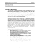
DMXQConnect for CR - User Guide Introduction INTRODUCTION WELCOME TO DMXQCONNECT! This User Guide is intended to familiarize you with the setup and use of the DMXQConnect routing software, the "human interface" for your new DMX distribution system. In preparing the User Guide, it has been assumed that you are reasonably familiar with the Microsoft Windows 95 operating system, and that Windows 95 is installed on your personal computer.
DMXQConnect for CR - User Guide About DMXQConnect Chapter 1: About DMXQConnect QUICK START Like most users of new lighting control equipment, you probably want to get your system up and running and performing useful work right away. You may already be familiar with the basic concepts of DMX signal line patching, or routing as it commonly known. You may be the person installing and commissioning a new system, not the end user.
DMXQConnect for CR - User Guide About DMXQConnect matrix devices that are commonly used in digital telephone switching systems carry out the patching function. Unlike most common local area networks, a DMX512 network often requires many separate data paths to handle the number of device addresses and codes necessary for medium to large-scale installations. Each data path can accommodate only 512 eight-bit codes.
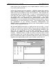
DMXQConnect for CR - User Guide About DMXQConnect Launching DMXQConnect, the user is presented with a combination status screen and work area made up of several window “panes”. It is here that the main work of creating a patch file is done. An old file can be retrieved from the archive, edited, and saved as a different one, or a new patch can be started from scratch.
DMXQConnect for CR - User Guide System Requirements and Installation Chapter 2: System Requirements and Installation SUMMARY: This Chapter describes: • What kind of PC you need to run DMXQConnect • How to install the DMXQConnect software • How to get the system communicating properly SYSTEM REQUIREMENTS OPERATING SYSTEMS DMXQConnect runs under Windows 95 and Windows NT. VIDEO DMXQConnect works best with SVGA displays at a resolution of 800x600 or 1024x768.
DMXQConnect for CR - User Guide System Requirements and Installation DMXPathfinder rack. Any COM port in the range of 1 to 4 will work. DMXQConnect supports baud rates of 300 to 19,200. PRINTER Patch files created by DMXQConnect can be printed out as hard copies. Any printer supported by Windows will work well. INSTALLING DMXQCONNECT 1. To begin, start Windows 95. Close all open applications and disable any virus-detection software. 2.
DMXQConnect for CR - User Guide System Requirements and Installation COMMUNICATIONS SETUP 1. Determine which COM port your computer will utilize for PC comm data communications with the DMXPathfinder rack (COM1, 2, 3 or 4). Don't attempt to use one that's already in use for an internal fax/modem or other device. If your mouse uses COM1, you shouldn't use COM3 for the comm link to the Pathfinder since it shares the same IRQ number as COM1. Choose COM2 instead.
DMXQConnect for CR - User Guide System Requirements and Installation ensure that the BACK/NORM switch on the Master Control Module is set to NORM. 7. Launch DMXQConnect. First click on View, DMX Pathfinder Options. Choose the DMXPathfinder Hardware Configuration tab. If you know how many input and output modules your system was supplied with, assign those values in the # of Input Cards / # of Output Cards fields. Click OK.
DMXQConnect for CR - User Guide System Requirements and Installation 10. Once the PC-to-Pathfinder communications function is working correctly as described previously in item 8, you should verify that all of the DMXPathfinder module frames are responding to commands from the PC. Click on View, DMXPathfinder Control, then choose the Patch Rack tab. This screen contains sixteen graphical red LEDs, each corresponding to a module frame in the largest possible DMXPathfinder system.
DMXQConnect for CR - User Guide System Requirements and Installation The window should now close and a moving bar graph will appear briefly under the send button. If it’s not convenient to call for the number at this time, click on Cancel and go on to Chapter 3. You can repeat this process when you have your authorization number, and all other functions except patch file transfers will work fine in the meantime.
DMXQConnect for CR - User Guide Getting Familiar with DMXQConnect Chapter 3: Getting Familiar with DMXQConnect SUMMARY Follow this Chapter to learn how to create, edit and save patch files and send them to the DMXPathfinder. Station and Source configuration is covered here. BEFORE WE GET STARTED Our discussion assumes that you, the user, have at least a basic understanding of Microsoft Windows 95, and how to navigate around its various menus and controls using a mouse.
DMXQConnect for CR - User Guide Getting Familiar with DMXQConnect PATCHING First go to the Patch Mode pane at the far right of your screen. Make sure that Offline is selected. This will ensure that DMXQConnect won’t try to send patch information to the DMXPathfinder until you are ready. We're now set to patch a few stations. First, left-click on one of the stations in the Non-Connected Stations pane.
DMXQConnect for CR - User Guide Getting Familiar with DMXQConnect access to the usual Windows commands of Undo, Cut, Copy, Paste and Delete, making it easy to edit this information. Since our description indicates that scrollers are attached to this station, let’s get the station icon to match, to make it easier to identify. Click on the ∇ button at the right of the Equipment Type box in the Station Detail pane and select Color Scroller from the choices offered.
DMXQConnect for CR - User Guide Getting Familiar with DMXQConnect TALKBACK If you are using IPS dimmers, Wybron Scrollers or any othe receiving equipment that uses XLR pins 4 and 5 for DMX “talkback”, you’ll need to enable the DMXPathfinder’s bi-directional mode for the station(s) involved. Click on the station(s) in either the Non-Connected or Connected panes that you wish to enable talkback for. Then, click the check-box Talkback Enabled in the Communications pane at the top of the screen.
DMXQConnect for CR - User Guide Getting Familiar with DMXQConnect Mode pane. The bar graph will confirm, as before, that the file transfer function was successful, the Backup patch is now stored in the Pathfinder’s backup patch memory. Now we have two files (albeit with the same data) stored in the DMXPathfinder’s internal memory. Let's try swapping patch configurations. Using the Main Menu, click on View, DMXPathfinder Options. Select the DMXPathfinder Patch Mode tab.
DMXQConnect for CR - User Guide Getting Familiar with DMXQConnect Select View from the main menu. Choose DMXPathfinder Options. Click on the DMXPathfinder Hardware Configuration tab. Notice that there are several panes of parameter information contained in this window.
DMXQConnect for CR - User Guide Getting Familiar with DMXQConnect There are two tabs, Show Specific and Defaults. The values entered under the Default tab will be used unless there are values entered in Show Specific. Show Specific values will supersede the Default values. DMXQConnect uses the values entered here to calculate the numbers displayed in the Address box of the Station Detail pane at the top of the working screen.
DMXQConnect for CR - User Guide Getting Familiar with DMXQConnect erase all information contained in the Show Specific tab so that the Default values will be used again. Remember that Show Specific values take precedence over Default values. When back in the main working screen, select a Connected or Non-Connected Station by clicking once on it. Then enter 1234 in the Device # box in the Station Detail pane at the top of the screen.
DMXQConnect for CR - User Guide Getting Familiar with DMXQConnect SOURCE CONFIGURATION Next we will assign working names to the various DMX sources (control console outputs) using the Configure, Source window and table. Access it from the main menu now. To add a new Source, Click the Add New button to clear the Source Name and Description boxes at the top of the window. Click on the Source Name box and type in the name of Source (e.g. Main Console DMX 1).
DMXQConnect for CR - User Guide Getting Familiar with DMXQConnect appear. Click Yes to confirm. Continue until all Sources in the table have been deleted. Note: Only the last Source in the table can be deleted with each Delete action. STATION CONFIGURATION Like Sources, Stations should be configured in advance to make your patching intuitive and easy. Go to the main menu and click Configure, Station. The Station Configuration window is similar to the Source Configuration window.
DMXQConnect for CR - User Guide Getting Familiar with DMXQConnect CONNECTED STATIONS DISPLAY To see which stations are connected to a specific source, simply click on the desired source in the Source pane. The Connected Stations display will change to show you only the stations connected to that Source. To remind you that you are only looking at the stations connected to a particular source, a green “LED” appears beside the Source referenced.
DMXQConnect for CR - User Guide Getting Familiar with DMXQConnect COMMAND LINE As an alternative to the “drag and drop” style of patching, you can work in a “Command Line” mode, without the mouse. Similar to many lighting control consoles, in this mode the numeric keypad on your keyboard can be used to assign stations to sources. TIP: You’ll find that the selecting the Detail view for both Non-Connected and Connected panes will make this process easier.
DMXQConnect for CR - User Guide Getting Familiar with DMXQConnect OPENING A DIFFERENT SHOW You may wish to work with a show other than the one that you used during your last session. If that is the case, choose File, Open Show from the main menu. A dialog box will open with the shows residing in DMXQConnect’s archives. Simply click on the desired show to highlight it, then click on the Open button.
DMXQConnect for CR - User Guide Command Reference Chapter 4: Command Reference SUMMARY This Section describes the function and use of DMXQConnect main menu commands. For a step-by-step procedure on how to create patch files and send them to the DMXPathfinder, refer to Chapter 3: Getting Familiar with DMXQConnect . FILE MENU The File menu deals with the functions of saving, retrieving, and deleting individual patch files. Exiting the DMXQConnect program is also done from the File menu.
DMXQConnect for CR - User Guide Command Reference Use the standard Windows 95 file management conventions to specify where you want the archive saved to. Restore from Backup A database that has been archived, can later be restored using this dialog box. When Restore From Backup… is selected, the user is first prompted to create a backup of the existing database. This is always recommended, since the Restore function will over-write all existing show files and system configuration data.
DMXQConnect for CR - User Guide Command Reference Splash: This refers to the initial screen and graphic seen when DMXQConnect is first started. You can specify a specific display time duration or have the splash hold until “a Key is Pressed or a Mouse is Clicked”. Display: You can choose to have the Command Line and Status Line display at the bottom of your screen, by click-checking the appropriate boxes.
DMXQConnect for CR - User Guide Command Reference Show Command Line & Show Status Bar You can choose to have the Command Line and Status Line display at the bottom of your screen, by click-checking the appropriate items. CONFIGURE MENU Station To add a new Station, click the Add New button to clear the Station Name and Description boxes at the top of the window. Notice that the next undefined station number is displayed in the station number box.
DMXQConnect for CR - User Guide Command Reference Click Yes to confirm. Note: Only the last Source in the table can be deleted with each Delete action. Equipment Type The Equipment Type selection provides information about a station and determines the icon displayed with the station. The list of available equipment types for selection is determined here. To add a new Equipment Type, click the Add New button to clear the Equipment Type and Description boxes at the top of the window.
DMXQConnect for CR - User Guide Command Reference To add a new Universe, click the Add New button to clear Universe and Description boxes at the top of the window. Click in the Universe # box and type in the number of the Universe. To delete any existing Universe, click on the desired Universe in the table. While it is highlighted, click the Delete button. A message to confirm your decision will appear. Click Yes to confirm.
DMXQConnect for CR - User Guide Diagnostics and Troubleshooting Chapter 5: Diagnostics and Troubleshooting SUMMARY This Chapter explains how to use DMXQConnect and the DMXPathfinder’s built-in diagnostic software to check for possible problems with file transfers or in the DMXPathfinder modules, to assist in verifying new DMX wiring installations and how to enter the system Access Code. It will also deal with what corrective action can be taken by the user.
DMXQConnect for CR - User Guide Diagnostics and Troubleshooting DMXPathfinder on the received file to ensure data integrity. The response message "Successful patch file transfer" should be seen in QConnect’s DMXPathfinder Event Log for every file send operation. If the message "Unsuccessful patch file transfer" appears, there is probably hardware trouble, most likely with the Master Control Module (MCM) in the Pathfinder. Replace the MCM with a spare unit and retry the file transfer.
DMXQConnect for CR - User Guide Diagnostics and Troubleshooting out “deep” testing of the DMXPathfinder crosspoint electronics, the terminal window will be faster. Both methods can be used for either test, however. These tests require that a "loopback connector" be plugged into either the optional insert jack on the face of the I/O module or the source/station jack at the far end of the installed DMX wiring. Loopback connectors are standard 5pin XLRs with pins 2&4, and 3&5 connected.
DMXQConnect for CR - User Guide Diagnostics and Troubleshooting test mode. To do a continuity test for a given output line, say Station #15, follow these simple steps: 1. Set the System Select button for your particular DMXPathfinder configuration, single-frame or multi-frame (default is multi-frame) 2. Select Output module as the I/O Card type. 3. Increment the I/O Card Address to 004 (since each I/O module has 4 inputs or outputs, output #15 will be on module #4) 4.
DMXQConnect for CR - User Guide Diagnostics and Troubleshooting the Frame or Master Control Module, and problems that affect every line in the system are most likely caused by a I/O bus cable connection. Make a note of the defective I/O channel and which lines are affected, then refer to the DMXPathfinder CR – Operation & Maintenance Manual for further assistance in correcting the fault. TERMINAL WINDOW METHOD Launch DMXQConnect and select View, DMXPathfinder Control from the main menu.
DMXQConnect for CR - User Guide Diagnostics and Troubleshooting Pressing "m" toggles the test mode between manual and automatic. In manual mode, the user manually increments or decrements the internal send/return bus channel to be tested (range 01-16), allowing a specific bus channel to be targeted for testing.
DMXQConnect for CR - User Guide Diagnostics and Troubleshooting plugged in to the I/O channel indicated on the display. Re-run the test on a known good input or output channel. In Automatic mode, pressing "i" will start running the test at the currently selected internal send/return bus channel, with the progress and results of every individual crosspoint test (Testing, Passed) displayed as it completes.
DMXQConnect for CR - User Guide Diagnostics and Troubleshooting letter keyboard commands for various functions. Three menu choices are shown: System Loopback Test, Access Code Input, and Serial Number and Access Code Support Status. Use upper-case characters to select from these items. A - ACCESS CODE INPUT When the DMX Pathfinder system is originally installed, and if/when the Master Control Module is replaced, the user must enter a unique access code to enable PC-to-Pathfinder patch file transfers.
DMXQConnect for CR - User Guide Index INDEX [ C [*] key · 22 [/] key · 22 [@] key · 22 [+] key · 22 [Caps Lock] key · 37 [Delete] key · 22 [Enter] key · 22, 27, 28, 29, 36 [Esc] key · 37 [Tab] key · 27 cable integrity · 31 cabling problems · 9 Card I/O Channel select · 35 channel · 17 Clear · 26 Clear command · 15 Clear Event Log · 25 Clear Existing Patch Mode and Normal Patch Data · 15 CMOS setup · 8 column · 20, 21 COM LED · 8 COM port · 7 COM Port · 5 COMM FAILURE · 8 Comm Port · 8, 26 Command Line
DMXQConnect for CR - User Guide File Menu · 24 File Transfer Errors · 30 Frame Control module · 32 Frame Control Module · 37 G ground loop problems · 7 H Index M Mainframe Serial # · 30 Manual · 33, 35 Manual/automatic mode · 35 Master Control Module · 7, 8, 31, 32, 37 Memory · 5 modify · 27, 28, 29 Mouse · 5 Multiframe · 33, 37 multiple frame · 34 Hard Disk Space · 5 N I I/O Card Address · 33 I/O card type · 33 I/O Channel to Test · 33 icon library · 28 icons · 4, 20, 28 Icons · 12, 28 incoming messa
DMXQConnect for CR - User Guide Show Command Line & Show Status Bar · 27 Show names · 24 show patches · 24 Show Specific · 17, 18, 28 signal common · 7 single frame · 33, 34 Single frame · 37 Single/multiframe system select · 34 software versions · 31 Sorting · 21 Source · 4, 6, 12, 21, 27 Source Configuration · 19 Source Name · 19, 27 source number · 27 Splash · 26 Start Device # · 17 station · 28 Station · 4, 12, 27 Station Configuration · 20 Station detail · 28 Station Detail · 12, 17 Station Icons · 20