
Instruction Manual

LCRC48GEP DMX RELAYCONTROLLER Configuration
INSTALLATION INSTRUCTIONS
1 -
Ensure that relay panel power is off (no indicator LEDs
glowing on the system motherboard). Remove the metal
cardframe cover.
2 -
Connect the DMX data line at the panel motherboard, with D-
to the black terminal and D+ to the red terminal. Attach the
shield drain wire to the SHIELD terminal.
3 -
If the DMX line is to be passed through to another panel,
attach the outgoing wires to the second set of data terminals.
4 -
If the relay panel is the last panel on the DMX wire run, it is
recommended that a 100 or 120 ohm 1/4W termination
resistor be installed between one pair of black and red data
line terminals.
5 -
Connect switch wiring to the A/B master switch input terminals
as required. The white terminal is switch common, the red is
switch "on", and black is switch "off". Connect the pilot lamp to
the yellow terminal adjacent to the first of the assigned relays.
6 -
Plug the controller card and one to four LCRD-12 driver cards
firmly into the cardframe.
7 -
Configure the controller card according to the following DIP
switch settings. Restore power.
8 -
Check that the power LED (between the DIP switch and the
three rotary switches) is glowing steadily. This indicates +5
volts present and correct microprocessor operation. A flashing
LED indicates a defective controller card.
9 -
Follow the program mode instructions to program the card for
optional DMX patch assignment and panel master switch
inputs.
10-
Apply the DMX control signal and observe that the receive
data LED (at left) is glowing. The LED will not glow if the
address set on the rotary switches exceeds either 512 or the
number of dimmer signals present on the data line, if the data
format does not conform to USITT-DMX512, or if the data
wires are reversed at the mother board.
11-
Verify relay operation with the DMX control system or the
card's test function, then use the checklist to ensure that
everything is set correctly before re-installing the cardframe
cover.
THRESHOLD SELECT DS-1
25% THRESHOLD (Trigger on at 30%, off at 20%) ON
75% THRESHOLD (Trigger on at 80%, off at 70%)
OFF
STATUS QUO
DS-2
ON (INFINITE HOLD) ON
OFF (2 SECOND HOLD) OFF
RELAY SELECTION DS-3 DS-4
1-12 RELAYS INSTALLED
ON ON
13-24 RELAYS INSTALLED
OFF ON
25-36 RELAYS INSTALLED ON OFF
37-48 RELAYS INSTALLED OFF OFF
CONTROL MODE DS-5
PATCH
Addressing determined by programmed patch for
each relay
ON
OFFSET
Panel start address determined by the address
select switches
OFF
SCAN RATE
DS-6
FAST SCAN (50 msec., 20 relays per second)
ON
NORMAL SCAN (100 mseC., 10 relays per second)
OFF
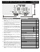
DIP Switch Settings
3.7"
10.3"
JP1
OPEN POSI TI ON SHOWN
J1
Rx D
x100 x10 x1
PWR
ADDRESS SELECT
RELAY SELECT PROGRAM
DS
ON = D OWN
PGM TST
x1
S1
x10
PROGRAM MODE
DS-7
Program Mode Enabled
ON
Program Mode Disabled (RUN MODE)
OFF
TEST MODE DS-8
Test Mode enabled
ON
Normal (RUN) Mode
OFF