
User guide

LCRC48GE DMX RELAY CONTROLLER Configuration
INSTALLATION INSTRUCTIONS
1 -
Ensure that relay panel power is off (no indicator LEDs
glowing on the system motherboard). Remove the metal
cardframe cover.
2 -
Connect the DMX data line at the panel motherboard, with
D- to the black terminal and D+ to the red terminal. Attach
the shield drain wire to the SHIELD terminal.
3 -
If the DMX line is to be passed through to another panel,
attach the outgoing wires to the second set of data
terminals.
4 -
If the relay panel is the last panel on the DMX wire run, it is
recommended that a 100 or 120 ohm 1/4W termination
resistor be installed between one pair of black and red data
line terminals.
5 -
Configure the controller card according to the following DIP
switch settings.
6 -
Plug the LCRC-48 controller card and one to four LCRD-
12 driver cards firmly into the cardframe. Restore power.
7 -
Check that the power LED (between the DIP switch and the
three rotary switches) is glowing steadily. This indicates +5
volts present and correct microprocessor operation. A
flashing LED indicates a defective controller card.
8 -
Set the 3 rotary address switches to the dimmer number
corresponding to the first relay in the panel. Note that
“000” (the factory default address) and “001” are
equivalent.
9 -
Apply the DMX control signal and observe that the receive
data LED (at left) is glowing. The LED will not glow if the
address set on the rotary switches exceeds either 512 or
the number of dimmer signals present on the data line, if
the data format does not conform to USITT-DMX512, or if
the data wires are reversed at the mother board.
10-
Verify relay operation with the DMX control system or using
the card's test function. Ensure that everything is set
correctly before re-installing the cardframe cover.
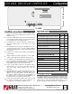
THRESHOLD SELECT DS-1 DS-2
20% THRESHOLD (Trigger on at 25%, off at 15%) ON ON
40% THRESHOLD (Trigger on at 45%, off at 35%) OFF ON
60% THRESHOLD (Trigger on at 65%, off at 55%)
ON OFF
80% THRESHOLD (Trigger on at 85%, off at 75%) OFF OFF
RELAY SELECTION DS-3 DS-4
1-12 RELAYS INSTALLED
ON ON
13-24 RELAYS INSTALLED
OFF ON
25-36 RELAYS INSTALLED ON OFF
37-48 RELAYS INSTALLED OFF OFF
RESERVED FOR FUTURE USE DS-5
RESERVED FOR FUTURE USE
DS-6
DIP Switch Settings
SCAN RATE
DS-7
FAST SCAN (50 msec., 20 relays per second)
ON
NORMAL SCAN (100 msec., 10 relays per second)
OFF
TEST MODE DS-8
Test Mode enabled
ON
Normal (RUN) Mode
OFF
3.7000"
10.3000"
RxD x100 x10 x1 PWR DS
When test mode enabled, relays are turned on one at a time as
selected by the rotary address switches
NOTE RE: GROUNDING
Pay particular attention to the grounding of the data line shield.
If the DMX controller grounds the shield, that is sufficient. If not,
a jumper wire must be installed between the data line SHIELD
terminal and the relay panel COM terminal. Only one such
ground connection should be made in any one data cable run.
05/03
Printed in Canada
support@pathwayconnect.com
www.pathwayconnect.com
Pathway Connectivity Inc., 480C - 36 Avenue S.E.,
Calgary, AB, T2G 1W4 Canada
tel (403) 243-8110 fax (403) 287-1281