DMXPathfinder LR Installation & User Guide Version 1.2 June 2000 Gray Interfaces 480C - 36 Avenue S.E. Calgary, AB, T2G 1W4 Canada Phone: Fax: (403) 243-8110 (403) 287-1281 E-mail: support@gray-interfaces.com Web site: www.gray-interfaces.
DMXPathfinder LR Contents CONTENTS INTRODUCTION ..............................................................3 WELCOME TO THE WORLD OF DMXPATHFINDER !.......................................3 CHAPTER 1: ABOUT DMXQCONNECT .............................................5 QUICK START ...............................................................5 WHAT IS DMXQCONNECT ? ......................................................5 CHAPTER 2: SYSTEM REQUIREMENTS AND INSTALLATION ..........................
DMXPathfinder LR CHAPTER 5: Contents DIAGNOSTICS ..................................................31 MODULE HEALTH CHECK .......................................................31 CROSSPOINT TESTS ..........................................................32 HARDWARE TESTS ...........................................................32 LOOPBACK TESTS ...........................................................32 Using the Diagnostics .................................................
DMXPathfinder LR About DMXQConnect INTRODUCTION WELCOME TO THE WORLD OF DMXPATHFINDER! This User Guide is intended to familiarize you with the installation, setup and use of the DMXPathfinder LR electronic DMX routing package and DMXQConnect routing software, the "human interface" for your new DMX distribution system.
DMXPathfinder LR About DMXQConnect • DMXPathfinder Installation leads you through all the steps necessary for a “clean” installation of your hardware. • DMXPathfinder Operations will familiarize you with all of the features of your new DMX router. • Maintenance and Testing offers troubleshooting tips and procedures to keep everything running smoothly.
DMXPathfinder LR Chapter 1: About DMXQConnect About DMXQConnect QUICK START Like most users of new lighting control equipment, you probably want to get your system up and running and performing useful work right away. You may already be familiar with the basic concepts of DMX signal line patching, or routing as it commonly known. You may be the person installing and commissioning a new system, not the end user.
DMXPathfinder LR About DMXQConnect resemblance to the old load patch panels that have been obsolete for almost twenty years. DMXQConnect is a software tool enabling the user to construct a virtual DMX data communications network on a personal computer.
DMXPathfinder LR About DMXQConnect Launching DMXQConnect, the user is presented with a combination status screen and work area made up of several window “panes”. It is here that the main work of creating a patch file is done. An old file can be retrieved from the archive, edited, and saved as a different one, or a new patch can be started from scratch.
DMXPathfinder LR About DMXQConnect than 512, and pops it into an Address cell for all to see, especially whoever is in charge of hanging lights and setting thumbwheel address switches. DMXQConnect also allows the user to specify which stations will be handling bi-directional communications; that is, where the connected equipment is capable of both sending and receiving data on separate wire pairs.
DMXPathfinder LR System Requirements and Installation Chapter 2: System Requirements and Installation SUMMARY: This Chapter describes: • What kind of PC you need to run DMXQConnect • How to install the DMXQConnect software • How to get the system communicating properly SYSTEM REQUIREMENTS OPERATING SYSTEMS DMXQConnect runs under Windows 95, Windows 98 and Windows NT. VIDEO DMXQConnect works best with SVGA displays at a resolution of 800x600 or 1024x768.
DMXPathfinder LR System Requirements and Installation COM PORTS The DMXQConnect program utilizes one asynchronous communications port (COM port) for file data transfer and control between the PC and the DMXPathfinder rack. Any COM port in the range of 1 to 4 will work. DMXQConnect supports baud rates of 19,200 and 38,400. PRINTER Patch files created by DMXQConnect can be printed out as hard copies. Any printer supported by Windows will work well. INSTALLING DMXQCONNECT 1. To begin, start Windows.
DMXPathfinder LR System Requirements and Installation The test is finished! Your PC has now been verified to run DMXQConnect properly. COMMUNICATIONS SETUP 1. Determine which COM port your computer will utilize for PC comm data communications with the DMXPathfinder rack (COM1, 2, 3 or 4). Don't attempt to use one that's already in use for an internal fax/modem or other device. If your mouse uses COM1, you shouldn't use COM3 for the comm link to the Pathfinder since it shares the same IRQ number as COM1.
DMXPathfinder LR System Requirements and Installation Select the COM port your PC is using for router communications, then the speed (the factory default baud rate is 38400 -- if you want to use 19200 instead, refer to the DMXPathfinder LR - Operation & Maintenance Manual or the configuration label behind the front cover of each Output Module. Ensure that the dip switch settings are the same on all Output Modules in the system.
DMXPathfinder LR System Requirements and Installation 1281 to obtain an authorization number. When you receive the 8-digit number, enter it into the Activation Key window and click OK. The window should now close and a moving bar graph will appear briefly under the send button. If it’s not convenient to call for the number at this time, click on Cancel and go on to Chapter 3.
DMXPathfinder LR DMXPathfinder Operations To get a fresh start, click on File, New Show. Enter the working title for the show file (20 characters maximum) in the box marked Name. An optional Description may be entered to provide additional information. When done click OK. PATCHING First go to the Patch Mode pane at the far right of your screen. Make sure that Offline is selected. This will ensure that DMXQConnect won’t try to send patch information to the DMXPathfinder until you are ready.
DMXPathfinder LR DMXPathfinder Operations status appear as the title of the Station Detail pane. Now click in the description area of the Station Detail pane and type in a description such as: Scrollers for cyc wash This description can be modified to include reminders or notes at any time by repeating the above process. Right-clicking on the description area gives you access to the usual Windows commands of Undo, Cut, Copy, Paste and Delete, making it easy to edit this information.
DMXPathfinder LR DMXPathfinder Operations SAVING You don’t need to do anything special to save a patch as everything you do is saved to your computer’s hard disk as you work. To create backups, see Backup Your Data later in this chapter. You’ve now completed the basics of creating a patch. In the chapters ahead we’ll discuss how to get your patch information from DMXQConnect to the DMXPathfinder as well as system configuration.
DMXPathfinder LR DMXPathfinder Operations for extended use. Use the Offline mode when you are not connected to the Pathfinder rack or do not wish to inadvertently send patch files the rack (note that Offline mode is always activated whenever QConnect is launched). In any case, the Patch Mode can be changed on the fly, at any time. Set the Patch Mode to Batch. Now press the Send Patch button ›. You should see a small bar graph appear to show you the progress of the patch transmission to the rack.
DMXPathfinder LR DMXPathfinder Operations Select View from the main menu. Choose DMXPathfinder Hardware Setup. Click on the DMXPathfinder System Configuration tab. Notice that there are several panes of parameter information contained in this window. The # of Input Modules and # of Output Modules define the actual size of your installation in terms of input and output lines; these parameters should only be set once when your system is commissioned, and changed only if the system is expanded.
DMXPathfinder LR DMXPathfinder Operations There are two tabs, Show Specific and Defaults. The values entered under the Default tab will be used unless there are values entered in Show Specific. Show Specific values will supersede the Default values. DMXQConnect uses the values entered here to calculate the numbers displayed in the Address box of the Station Detail pane at the top of the working screen.
DMXPathfinder LR DMXPathfinder Operations It is unnecessary to enter any universe information under the Show Specific tab unless the requirements of, say, a touring show requires different values to be used. When that show moves out, be sure to use the Delete button to erase all information contained in the Show Specific tab so that the Default values will be used again. Remember that Show Specific values take precedence over Default values.
DMXPathfinder LR DMXPathfinder Operations text editing conventions of Windows apply, including the right-click editing tools. When your editing is complete, click the Update button or use the [Enter] key to complete the modification to the Sources table. Click on Close when you are done. The number of Sources displayed is determined by the number of Input modules in your system, as specified in Hardware Setup, System Configuration.
DMXPathfinder LR DMXPathfinder Operations workspace you find useful. You can enlarge the pane to see more. Similarly the individual columns of the table can be resized in the same way. Move the cursor to the table column heading area, between two columns. Again the cursor should change to the resize cursor. When it does, click and drag the column border until it is the desired width.
DMXPathfinder LR DMXPathfinder Operations Maximize the report window so that it fills the screen. If the report form looks empty, you probably don’t have any stations patched. Close the report window and patch a few stations before re-opening report. Controls for the report display appear along the bottom of the window. COMMAND LINE As an alternative to the “drag and drop” style of patching, you can work in a “Command Line” mode, without the mouse.
DMXPathfinder LR DMXPathfinder Operations data with the backup copy. Note that this process archives all show patches and configuration data. OPENING A DIFFERENT SHOW You may wish to work with a show other than the one that you used during your last session. If that is the case, choose File, Open Show from the main menu. A dialog box will open with the shows residing in DMXQConnect’s archives. Simply click on the desired show to highlight it, and then click on the Open button.
DMXPathfinder LR Chapter 4: DMXPathfinder Operations Command Reference SUMMARY This Section describes the function and use of DMXQConnect main menu commands. For a step-by-step procedure on how to create patch files and send them to the DMXPathfinder, refer to Chapter 3: Getting Familiar with DMXQConnect. FILE M ENU The File menu deals with the functions of saving, retrieving, and deleting individual patch files. Exiting the DMXQConnect program is also done from the File menu.
DMXPathfinder LR DMXPathfinder Operations Use the standard Windows file management conventions to specify where you want the archive saved to. Restore from Backup A database that has been archived, can later be restored using this dialog box. When Restore From Backup… is selected, the user is first prompted to create a backup of the existing database. This is always recommended, since the Restore function will over-write all existing show files and system configuration data.
DMXPathfinder LR DMXPathfinder Operations Splash: This refers to the initial screen and graphic seen when DMXQConnect is first started. You can specify specific display time duration or have the splash hold until “a Key is Pressed or a Mouse is Clicked”. Display: You can choose to have the Command Line and Status Line display at the bottom of your screen, by click-checking the appropriate boxes. Comm Port: This screen defines the hardware connection parameters between your PC and the DMXPathfinder.
DMXPathfinder LR DMXPathfinder Operations automatically highlit so that you may continue the editing process. Click on Close when complete. Station To edit a Station, first click on it. Click in the Station Name box and type in the name of Station (e.g. Main Console DMX 1). Use the [Tab] key or click in the Description field. An optional description may be entered here. The regular text editing conventions of Windows apply, including the right-click editing tools.
DMXPathfinder LR DMXPathfinder Operations placed in the Program Files\QConnect\Icons directory for easy access from DMXQConnect use. Universe DMX Universes need to be set up properly to take full advantage of the optional DMX address calculation features in DMXQConnect. There are two tabs, Show Specific and Defaults. The values entered on the Defaults tab will be used unless there are values in Show Specific. Show Specific will supersede the Default values.
DMXPathfinder LR DMXPathfinder Operations As well, reports can be exported to a variety of formats including Lotus, Excel and Word, by clicking on the “suitcase” button and selecting the format desired.
DMXPathfinder LR Chapter 5: Diagnostics Diagnostics SUMMARY This Chapter explains how to use DMXQConnect and the DMXPathfinder’s built-in diagnostic software to check for possible hardware faults in the Pathfinder modules, and to assist in verifying new DMX wiring installations. It will also deal with what corrective action can be taken by the user. For a more detailed troubleshooting procedures please refer to Chapter 8: Maintenance & Troubleshooting.
DMXPathfinder LR Diagnostics CROSSPOINT T ESTS The functional backbone of the DMXPathfinder hardware is an electronic crosspoint matrix device, which provides the DMX signal patching function. Two such devices are included on the XPU (Crosspoint Unit) PC card in each Output Module; one for transmitted signals and the other for received (talkback) signals. The crosspoint devices are programmed in terms of both operational arrangement and input/output configuration by the module CPU.
DMXPathfinder LR Diagnostics When a loopback test is initiated, the DMXPathfinder’s Output Module CPU generates a simulated DMX signal and creates a routing path through the Pathfinder electronics according to the I/O parameters that the user has assigned. The signal is transmitted on the selected output line’s send data pair (XLR pins 2 and 3) and received back on the same module’s return data pair (XLR pins 4 and 5).
DMXPathfinder LR Diagnostics diagnostics are started all DMX data moving through the selected DMXPathfinder module will be cut off until you exit from the diagnostics or close the DMXPathfinder Control window. X -- Crosspoint Tests Pressing "T" displays the Crosspoint Tests sub-menu. Pressing S or R selects the send (transmit) crosspoint or return (receive) crosspoint device test menu.
DMXPathfinder LR N - S - T - Diagnostics numeric loopback channel select Pressing N then entering the desired I/O channel to test (range 0116 for inputs, 01-32 for outputs), allows a specific I/O channel to be targeted for testing. This mode might be used to check for a suspected faulty cable. start test Pressing S after an I/O channel is displayed will initiate a complete check of the Pathfinder’s internal electronics and interconnections as they relate to the selected channel.
DMXPathfinder LR Diagnostics firmware version are always shown when the main diagnostics menu is displayed. A -- Access Code Input/Display Pressing ‘A’ will display the Access Code sub-menu, as well as the currently stored six-character access code and whether or not it is valid. If the word ‘valid’ appears after the code, no action is required. If ‘invalid’ appears, contact the factory to obtain the correct access code for that particular Output Module.
DMXPathfinder LR Diagnostics yes” when the fan is on. Note that to conserve fan life, the fan will operate only when one or more channels in the Output Module are patched. T - thermostat setup and status display Pressing T displays the temperature status command menu, the current overtemperature settings and the current Output Module internal temperature. Press ‘I’ to change the overtemperature threshold, which should be about 5 degrees C above the normal operating temperature of your installation.
DMXPathfinder LR Chapter 6: Installation & Assembly Installation and Assembly SUMMARY This section describes how to correctly assemble the DMXPathfinder LR hardware into an equipment rack and connect permanently installed external wiring. To ensure a trouble-free installation, you should follow this sequence: 1. 2. 3. 4. 5. 6. 7. 8. 9.
DMXPathfinder LR Installation & Assembly the same rack, allow for at least a 1U vent panel at the top and bottom of the rack. Power Requirements -- A single phase power source (50 or 60Hz, 100240VAC, at 0.1A per Input Module and 0.25A per Output Module) must be provided to the DMXPathfinder LR equipment rack. It is recommended that no more than ten I/O modules be connected to one power circuit due to the startup current requirements of their switch-mode power supplies.
DMXPathfinder LR Installation & Assembly Modules and 4U Output Modules to be installed, then add at least 2U for vent panels and allowance for power bars, connector panels or other accessories if required. Louvered, locking front and rear doors are recommended. Locate the rack such that at least 3 feet of clearance is allowed at the front, 2 feet at the back, and sufficient clearance at one side (preferably the left) to permit service access to the internal cable connections.
DMXPathfinder LR Installation & Assembly boards mount directly to the rear of each output module using five 6-32 standoffs and screws. They electrically connect to each Output Module with eight 25-pin D-style connectors, therefore a certain amount of force is required to mate the two parts. Ensure that all 8 connectors are fully mated and that the board is resting on the standoffs before installing the five screws.
DMXPathfinder LR Installation & Assembly each module, and use 8-32 screws to attach the rack mount ears to the sides of each Input and Output Module. If P2020 type termination boards are to be used, mate them to each Output Module and fasten with 5 x 6-32 screws. Using one power cord, power up each Input and Output Module one at a time and verify that the main power LEDs illuminate. Remove the four adhesive rubber feet from the bottom of each module.
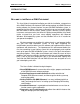
DMXPathfinder LR PORT H 1 2 3 4 5 PORT G 1 2 3 4 5 Installation & Assembly PORT F 1 2 3 4 5 DMX INPUTS PORT E PORT D 1 2 3 4 5 1 2 3 4 5 PORT C 1 2 3 4 5 PORT B 1 2 3 4 5 PORT A 1 2 3 4 5 Input Module #1 (inputs 1 - 8) POWER INTER-MODULE BUS 100-240V 50/60Hz PORT H 1 2 3 4 5 PORT G 1 2 3 4 5 PORT F 1 2 3 4 5 DMX INPUTS PORT E PORT D 1 2 3 4 5 1 2 3 4 5 J2 PORT C 1 2 3 4 5 PORT B 1 2 3 4 5 J1 OUTPUT 5-8 J10 OUTPUT 1-4 J9 CABLEBIN J4 J3 OUTPUT 13-16 OUTPUT 9-12 OUTPUT 21-24 OUTPUT
DMXPathfinder LR Installation & Assembly Remember that for systems with only one input module, only the CABLE A jacks need ribbon cable jumpers and the bus terminator installed. I/O C ABLE CONNECTION Strip back about 3 inches (8cm) of cable jacket and braid shield from each input or output cable. Apply a 2.5" (6.5cm) piece of 1/16" heat shrink to the drain wire and a 1" (2.5cm) piece of 3/8" heat shrink over the exposed braid ends where each cable was stripped.
DMXPathfinder LR Installation & Assembly PC-COM C ABLE CONNECTION Each Output Module is provided with an 8-position rear-mounted terminal block for connection to the system’s personal computer. Two separate ports are provided: an RS232 port and an RS485 port. There is also a 10VDC phantom power supply available for powering an optional RS232/485 converter.
DMXPathfinder LR Installation & Assembly Pin 5 – Power & Signal Common (connect to “COM” terminal) Pin 6 – Data Set Ready Pin 7 – Request to Send Pin 8 – Clear to Send Pin 9 – Ring Indicate Only pins 2, 3 and 5 are required to connect for RS232 communications. If the RS232/485 converter is to be used, it is strongly recommended that a 3pair or 4-pair RS422/485 rated twisted pair data cable is used for the connection to the DMXPathfinder LR. Category-5 UTP cable works well.
DMXPathfinder LR Installation & Assembly T ESTING THE INSTALLATION Once all connections are made and inspected for errors, you can power up the DMXPathfinder LR modules in the equipment rack. With no DMX source signals present, all eight red Isolated Power LEDs on the face of each Input Module should be illuminated. On each Output Module, the green Processor OK and Main 5V Power LEDs should be illuminated. If, in addition, the green Crosspoint OK LED is on, this does not indicate a problem.
DMXPathfinder LR DMXPathfinder Operations MAINTENANCE AND TESTING PREVENTIVE M AINTENANCE The DMXPathfinder LR will require a minimal amount of ongoing preventive maintenance to ensure a long, trouble-free life for the equipment. Maintenance will consist primarily of periodic cleaning and inspection of the distribution rack. CLEANING Rack cleaning should be carried out once per year.
DMXPathfinder LR DMXPathfinder Operations circuit card with a spare unit and re-test. Powering down the entire DMXPathfinder, or at least the specific module, is recommended before removing or inserting cards. To replace an Output Module card, first remove loosen the four front panel Phillips screws and the panel, then grasp the card stiffener bracket (or ejector handles), and pull the card straight out of the module chassis.
DMXPathfinder LR DMXPathfinder Operations Fluke 650 Cable Meter -- Please refer to the manufacturer's user's manual for detailed instructions and theory before attempting to use this instrument. It’s not obvious to the first time user! The Fluke 650 is provided with a battery-powered remote plug-in unit, a set of 2 adapter cables (RJ45 to 5-pin XLR) and an AC adapter.
DMXPathfinder LR DMXPathfinder Operations ADVANCED T ROUBLESHOOTING As described earlier, basic troubleshooting usually involves isolating a troublesome or defective opto-repeater circuit, card or module and replacing it with a known good one. It may also include checking for obvious things such as incorrect addressing or DMX protocol incompatibility with DMX receiving devices, absence of a line terminator, defective DMX patch cables, or even incorrect control console configuration.
DMXPathfinder LR DMXPathfinder Operations If the above tests yield passing results and the problem persists, it may be necessary to use the Fluke LAN Cable Meter to do a high-frequency analysis of the suspect cable runs. This test will quickly indicate any anomalies having to do with cable impedance and capacitance that would result in excessive signal distortion or attenuation.
DMXPathfinder LR Chapter 7: DMXPathfinder Operations DMXPathfinder Operations SYSTEM OVERVIEW The entertainment industry standard DMX512 data protocol is being utilized for remote control of a wide range of lighting and effects equipment within theatres, television studios, theme parks and other facilities. Increasingly, a high degree of integration of this type of equipment within a common control network is required.
DMXPathfinder LR DMXPathfinder Operations To accommodate the above requirements, a typical DMX Distribution System consists of the following major components: .5 Remote DMX input stations; in the control room, on the stage, and in other locations, for connection of control consoles or other DMX source units. .6 Remote DMX output stations, located on FOH lighting positions, onstage lighting pipes, and spaced evenly around the stage or studio, for connection of DMX-controlled (receiving) equipment. .
DMXPathfinder LR DMXPathfinder Operations PATCHING T ECHNIQUES Proper use of the DMX Distribution System involves the electronic routing, or patching, of one or more source DMX signal lines to one or more output (receiving) stations, via the Input and Output Modules in the distribution rack (DMXPathfinder). This technique eliminates the possibility of accidentally creating an illegal "star" wiring configuration in the DMX Distribution System.
DMXPathfinder LR DMXPathfinder Operations FRONT PANEL CONNECTORS Since each Input Module in the system includes eight faceplatemounted male XLR jacks, it is possible to use these as alternate DMX inputs. Some installations use them for primary DMX input, via short patch cables from an auxiliary DMX input panel mounted adjacent to the Input Module. In these cases, the rear input terminal blocks are not used.
DMXPathfinder LR DMXPathfinder Operations Remember that end-of-line termination (100-120 ohms) is necessary on all individual DMX cable runs. Source lines are all permanently terminated by integral resistors in each Input Module, and likewise the auxiliary (return) wire pair of each outgoing station line is terminated in each Output Module. The transmit (send) wire pair of each station line, however, must be manually terminated at its final destination receiving device.
DMXPathfinder LR DMXPathfinder Operations All red LED indicators should be on steady in normal usage. A flashing Main 5V Status LED warns of a problem with one of the Output Module power supplies in systems where redundant supplies are fitted. If the LED is off, there is no power present (no other indicators will be on either). A flashing green Processor OK LED indicates processor failure for that module.
DMXPathfinder LR Index INDEX customize · 16 Cut · 14 [ C [*] key · 22 [/] key · 22 [@] key · 22 [+] key · 22 [Delete] key · 22 [Enter] key · 22, 27, 28 [Tab] key · 26, 27 CABLE A IN · 42 CABLE A(B) THRU · 42 CABLE B IN · 42 cabling · 40 Card Replacement · 46 Cat-5 UTP cable · 44 channel · 18 circuit boards · 46 Cleaning · 46 Clear command · 16 Clear Event Log · 25 Clear Patch · 16 CMOS setup · 11 column · 21 COM · 44 COM port · 9, 10, 44 COMM FAILURE · 11 Comm Port · 10, 26 Command Line · 22, 26 Comma
DMXPathfinder LR Index edit icons · 28 End Device # · 18 Environmental Considerations · 37 EPROM · 34 Equipment Name · 20 equipment rack · 37, 38, 40, 41, 45 Equipment Type · 14, 27 Event Log · 25 events · 25 Excel · 21, 29 Exit · 25 increment loopback channel selected · 33 indicator tests · 35 Input Module · 32, 39, 41, 45, 55 input stations · 52 Inspection · 46 Installation · 8, 37 installer · 38 Installing DMXQConnect · 9 Inter-Module Bus connector · 42 IRQ · 10, 11 Isolated Power · 10 Isolated Power
DMXPathfinder LR printer · 9, 21 processor failure · 56 Processor LED · 10 Processor OK LED · 10, 45, 47, 55, 56 Q Quick Start · 5 R Rack cleaning · 46 Rack Placement · 38 Rack Sizing · 38 receive data · 56 Receive Data LEDs · 55 Refresh · 25 Relative humidity · 37 Rename Show As · 24 Reports · 21, 28 Reset · 16 RESET · 47 Reset and Upload File · 25 restore · 25 Restore from Backup · 22, 25 ribbon cable · 40, 42 Rosco/ET IPS dimmers · 15 RS232 · 10, 43, 49 RS232/485 converter · 44 RS422 · 7 RS422/485 seri