DMXPathfinder MR Users Guide Version 1.1 October 1998 Gray Interfaces 480C - 36 Avenue S.E. Calgary, AB, T2G 1W4 Canada Phone: Fax: (403) 243-8110 (403) 287-1281 E-mail: support@gray-interfaces.com Web site: www.gray-interfaces.
DMXPathfinder LR Contents CONTENTS INTRODUCTION ..............................................................2 WELCOME TO THE WORLD OF DMXPATHFINDER !.......................................2 CHAPTER 1: INSTALLATION AND ASSEMBLY ......................................3 SUMMARY ...................................................................3 BEFORE STARTING ...........................................................3 RACK SIZING AND PLACEMENT ...................................................
DMXPathfinder LR Introduction INTRODUCTION WELCOME TO THE WORLD OF DMXPATHFINDER! This Installation Guide is intended to walk you through a typical installation. In preparing the User Guide, it has been assumed that you are reasonably familiar with the DMX512 and the various wiring methods associated with RS422/485 based protocols.
DMXPathfinder LR Installation & Assembly Chapter 1: Installation and Assembly SUMMARY This section describes how to correctly assemble the DMXPathfinder MR hardware into an equipment rack and connect permanently installed external wiring. To ensure a trouble-free installation, you should follow this sequence: 1. 2. 3. 4. 5. 6. 7. 8. 9.
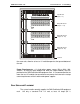
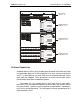
In pu t Mo d ul e Isolated Power A B C D E F G I/O OPTO- REPEAT ER UNITS XPU I/O OPTO-REPEATER UNI TS XPU I/O OPTO-REPEATER UNIT S Input Module (inputs 1 - 8) H SYSTEM RESET Receive Data Talkback Data Isolated Power Talkback Data TransmitData A 1 2 3 4 9 10 11 12 19 5 6 7 8 13 14 15 16 20 21 22 29 30 31 32 6 7 8 15 16 Isolated Power Talkback Data TransmitData B Isolated Power Talkback Data TransmitData C 17 18 23 24 Isolated Power Talkback Data TransmitData
DMXPathfinder LR Installation & Assembly recommended). To calculate minimum height, add up the number of 2U Input Modules and 4U Output Modules to be installed, then add at least 2U for vent panels and allowance for power bars, connector panels or other accessories if required. Louvered, locking front and rear doors are recommended.
DMXPathfinder LR Installation & Assembly Model P2020 32-way terminal block transition boards are the most commonly used method of connecting the DMX output station cabling. These boards mount directly to the rear of each output module using five 6-32 standoffs and screws. They electrically connect to each Output Module with eight 25-pin D-style connectors, therefore a certain amount of force is required to mate the two parts.
DMXPathfinder LR Installation & Assembly Unpack all of the DMXPathfinder MR system modules and accessories and arrange on a flat surface. First, locate the package of screws supplied with each module, and use 8-32 screws to attach the rack mount ears to the sides of each Input and Output Module. If P2020 type termination boards are to be used, mate them to each Output Module and fasten with 5 x 6-32 screws.
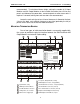
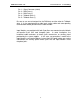
DMXPathfinder LR Installation & Assembly POWER IN DMX INPUTS PORT E PORT D PORT H PORT G PORT F 1 23 4 5 12 34 5 12 34 5 1 234 5 1 2 34 5 INTER-MODULE BUS PORT C PORT B PORT A 12 34 5 12 34 5 1 23 4 5 Input Module (inputs 1 - 8) 100-240V 50/60Hz J2 J1 OUTPUT 5-8 J10 J9 OUTPUT 1-4 CABLE B IN J4 POWER IN CABLE A IN J3 OUTPUT 13-16 OUTPUT 9-12 OUTPUT 21-24 OUTPUT 17-20 OUTPUT 29-32 OUTPUT 25-28 J6 INTER-MODULE BUS J5 J8 DMX Pathfinder MR 100-240V 50/60Hz 32-WAY OUTPUT MO
DMXPathfinder LR Installation & Assembly Pin 1 -- Signal Common (shield) Pin 2 – DMX Data (-) Pin 3 – DMX Data (+) Pin 4 – Talkback Data (-) Pin 5 – Talkback Data (+) Be sure to use one twisted pair for the DMX data and the other for Talkback data. It is also good practice to label each station cable and corresponding terminal block header position with the cable number. Input Modules are provided with both 5-position rear-mounted terminal blocks and parallel 5-pin XLR male faceplate jacks.
DMXPathfinder LR Installation & Assembly Patching To assign outputs to inputs, first remove the front cover to access the Crosspoint Card (E). B ROUTER ASSIGNMENT SW1 thru SW32 Eachswitchsetsroutingfor oneDMXoutputline.Switch positionnumbers"1"thru"8" correspondtoDMXinputs"A" thru"H".Donotusepositions "0"&"9". C E x a m p e l: Torouteinput"D"tooutput25 setSW25to"4".
DMXPathfinder LR Index Chapter 2: Maintenance & Testing T ESTING THE INSTALLATION Once all connections are made and inspected for possible errors, you can power up the DMXPathfinder MR modules in the equipment rack. With no DMX source signals or talkback signals present, all eight red Isolated Power LEDs on the face of the Input Module should be illuminated.
DMXPathfinder LR Index To replace an Output Module card, first remove the four front-panel Phillips screws and the cover panel, then grasp the card stiffener bracket (or ejector handles), and pull the card straight out of the module chassis. Carefully align the replacement circuit board into the chassis' left and right card guides and slide the unit in until it protrudes about 5mm, then push the module firmly into its mating backplane receptacles.
DMXPathfinder LR Index The Fluke 650's signalling is not compatible with the DMXPathfinder MR electronics or any other DMX generating or receiving equipment. Thus its usage should be confined to the cable installation only. Goddard Design Li'l DMX'ter -- This useful instrument can test most aspects of the DMX Distribution System, from wiring continuity to signal propagation through the DMXPathfinder electronics.
DMXPathfinder LR Index carried out. Try swapping input or output cable connections on the back of the DMXPathfinder modules with adjacent ones to use a different receiver and transmitter circuits. Next, a DMX tester should be used to either transmit DMX in place of the control console, or receive DMX in place of the receiving device(s). Check the receiving device by connecting the DMX tester directly to it in transmit mode.
DMXPathfinder LR Index INDEX Output Module · 5, 6, 7, 10, 11, 14 A F Advanced Troubleshooting · 13 Ambient temperature · 3 Assembly · 3 Fan · 3 Frequency Generator · 13 P2020 · 6, 7 Patching · 10 Power Requirements · 4 Processor OK LED · 11 G B P Goddard Design · 13 R bus terminator · 7 H C CABLE A IN · 7 CABLE A(B) THRU · 7 CABLE B IN · 7 cabling · 6 Card Replacement · 11 control console · 13 Cooling · 3 Crosspoint card · 10 Crosspoint OK LED · 11 D diagnostic instruments · 12 Digital Volt/Oh