Pathport Manager 5 User Guide © Pathway Connectivity 2010 1439 17 Ave SE Calgary AB T2G 1J9 403-243-8110 www.pathwayconnect.
Overview .........................................................................................................................3 Installation, NIC Configuration and Start Up ....................................................................4 Log-in Screen..............................................................................................................4 Node Discovery...............................................................................................................
Overview Pathport Manager 5 is a software program used to configure, troubleshoot and monitor Pathport® DMX-over-Ethernet nodes manufactured by Pathway Connectivity. Pathport nodes are used primarily in entertainment and architectural lighting systems employing DMX512 as the control protocol. Pathport Manager 5 will configure properties for all Pathport one-port, two-port, four-port and eight-port nodes using a firmware version of 3.0.2.x or higher.
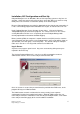
Installation, NIC Configuration and Start Up Pathport Manager 5 runs on Windows, Mac or Linux operating systems using Java 1.6 or higher. Go to java.com to verify your version is up-to-date. Mac users must be using 64-bit processors and must set Java SE 6 (64-bit) as the default engine. Because Pathport Manager must often be downloaded using slow or poor connections, it is not a self-installing program with embedded Java engine, in order to reduce file size.
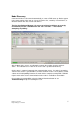
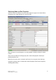
Node Discovery Connected nodes are discovered automatically as soon as PM5 starts up. Nodes appear in the upper portion of the start up screen, the Device List, sorted by ‘Current Name’, or whatever column was last used to sort devices. The first time Pathport Manager 5 is run on an existing installation, we strongly recommend you save a Showfile from the “File > Save As…” menu before attempting any editing. At the bottom of the screen, an indicator bar reports the number of nodes and their status.
Displaying Node and Port Properties Click on a node in the Device List and its base properties appear in the lower Device Properties pane, along with tabs for each of its ports. Both the Device List and Properties are easily up/down sorted by clicking on column headers. Enter text in the Filter box to display only those nodes with properties that fully or partially match the text. More than one node can be selected in the Device List, using the Ctrl or Shift keys.
Editing Base Node Properties The first time Pathport Manager 5 is run on an existing installation, we strongly recommend you save a Showfile from the “File > Save As…” menu before attempting any editing. When using nodes with firmware of 3.0.2.x or lower, the patch settings will not be retrieved or saved. Properties are edited in the lower Device Properties pane. The property’s current value is shown under the Current Value column. Changes are made under the New Value column.
Editing Port Properties Port properties are edited using the same conventions as node properties. Property definitions are given in Appendix B. Not all properties are shown by default. Port properties for multiple nodes may be edited simultaneously.
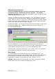
Setting a Basic DMX Patch The DMX Patch tab shows a listing of input and output ports. Each port on a node has its own listing. Use the filter search to find ports on a specific node. Input Patch Assignment Input ports receive DMX from lighting boards, architectural controllers and other DMX sources. Although the same universe number can be used by different input ports, it’s better practice to assign a different universe to each input.
Simply select the new patch from the list to assign it to the port. Patches that are not being used by a port are shown with the tag “(no input)”. Choosing “Disable” will clear the check box under DMX Enable, and the port will ignore any DMX it receives. Input ports are always assigned a standard universe for the patch. Custom patching is always done at the output port. Once the input patch assignments are queued, click on “Send Patches to Ports” to update the nodes.
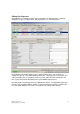
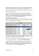
Showfiles PM5 will save and restore showfiles containing all or some of the configuration and patch information used by the connected nodes. If all nodes are selected, then all custom patches, including ones not assigned to a node, will also be saved. This method allows the user to build up a library of patches for future use. Showfile names are not saved by the nodes, only the configuration and patch information.
A non-critical warning will be reported when saving shows that include nodes running older firmware. In the case above, the nodes at 10.0.0.21 and10.0.0.100 both lack two properties, so PM5 has ignored them. Since both the base node and each individual port may be lacking properties, this list can be quite long when saving from nodes using older firmware. Showfiles are stored in the /showfiles subdirectory of Pathport Manager 5.
Off-line Showfile Editing Showfiles are saved in a CSV (comma-separated value) format, and may be edited in most spreadsheet programs. Patches as well as node parameter values may be changed. The format is fairly basic, but it is possible to break the showfile. Pathport Manager 5 will recover as much information as possible. Auto Backup and Restore Pathport Manager 5 provides a background autosave feature.
Firmware Upgrades To upgrade a node, highlight it in the Upgradable Devices List. Choose “Select Firmware” to manually choose from a list, or choose “Select Latest” for PM5 to automatically queue the latest version available. If more than one node is highlighted, only the “Select Latest” button will be available. Click on “Send Firmwares” to commit the new firmware to the nodes. A transaction window will open, providing progress updates on the upgrades.
Advanced Configuration Pathport Manager 5 provides access to a number of advanced features including custom patching with merge and priority support, DMX-over-Ethernet protocol selection, signal loss behavior, DMX output speed and more. The most commonly used advanced feature is custom patching. Universe Editor DMX limits the number of output devices to 512, which means no DMX receiving device may have an address higher than 512.
Building from Existing Patches Editing a Standard Universe will cause the automatic creation of a custom patch. Click “New” and enter a name for the custom patch beside “Universe Name”. Click on either “HTP Merge” or “Priority” and select a standard universe patch from the pop-up list. If any Custom patches already exist, they will be shown at the top of the list, and can also be selected.
To prioritize inputs, use the / symbol (the division slash). Inputs listed first (i.e. further left on the command line) are given higher priority. To prioritize universe 3 over universe 2 over universe 1 (again, note the final dash to indicate a range): 1-512*3.1-/2.1-/1.
A comma may be used to delimit between a series of channel ranges. To have the first five channels use universe 1, and the second five use the last five channel of universe 3: 1-5*1.1-,11-10*3.508- The comma, slash and plus sign can be used in conjunction with one another. By starting the command line with + or /, it is possible to add to patch, as in this example, building on the patch above: +1-10*5.100-/25.
Directly Editing a Patch Channel and priority values can also be directly entered into the spreadsheet by clicking on a cell and typing in the number. Priority cells will only accept values between 1 (high) and 8 (low). Ranges may be entered by typing in the start value, then selecting a range of cells below. An entire column may be selected by clicking on the header.
This will expand a hidden sidebar called Universe Statistics. (Clicking the left-pointing arrow will hide it again.) The upper window shows how many inputs and outputs are using a specific standard universe patch. The lower window shows the current custom universes, the number of outputs using a specific patch, and whether it is equivalent to a standard patch. Selecting a custom universe will cause its channel information to be shown on the right.
Advanced Node Properties A full list of node properties is found in the appendix, but some require a more detailed description and explanation. Alternate ArtNet Mapping ArtNet universe selection is based on two 16-step rotary switches. One switch sets the subnet, while the other sets the universe, so that valid universe numbers range from 0-0 to F-F. This arrangement does not readily translate to the linear, decimal-based numbering used by Pathports. The common problem is with ArtNet universe 0-0.
is very difficult to conceptualize, and will likely lead to unexpected results and a headache. We feel the best solution is to choose one priority scheme or the other. If sACN Input Priority is disabled (default), all priority and channel patching should be done at the output port. If sACN Input Priority is enabled, we strongly recommend patching all input and all outputs to universe 1, and managing all priorities through the port property “E1.31 sACN Input Priority Level”.
Valid priority levels range from 1 to 200, with 200 being the highest priority. Default value is 100. The value is set at the input port only. Two sources set to the same priority level will be merged together. When sACN is active with priority enabled, all other protocols are ignored. Input priority is a component of the E1.31 streaming ACN standard. sACN Input Priority Channel (Magic Channel) This value only applies if the “sACN Input Priority” property of the outputting node is ‘Enabled’.
Signal Loss Fade, when enabled, causes the port to use the Signal Loss Fade Time value (in milliseconds) to fade all channels to zero. If Signal Loss Fade is disabled, all channels will instantly drop to zero once the Signal Loss Hold Time has elapsed. Signal Loss Fade should not be enabled on ports feeding moving lights. Signal Loss Port Shutdown, when enabled, shuts off the port once other signal loss behaviors are complete, so no DMX data will be sent at all until inputs are restored.
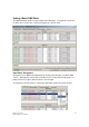
the appendix. Here is a portion of the column lists for the Device List and for the Output Port portion of the DMX Patch. By selecting or deselecting the “Visible?” checkbox, highly customized views can be created. Pathport Manager notes these changes on the fly, and records them into the current view. Specialized views should be saved individually as soon as they’ve been created. There is no limit to the number of views a user may make.
Troubleshooting Network Interfaces – Online yet Questionable The most common problem when using a Pathport system is an IP addressing mismatch. If a node is shown as being “Online” but its status is “Questionable”, the problem is almost always due to a mismatch between the computer’s IP (and subnet mask) and the IP and subnet mask used by the node. To determine what IP and subnet mask is used by your computer, click on the “Network Interfaces” button in the lower right-hand corner.
Virtual Console – Output Testing Pathport Manager 5 provides, from the Tools menu, a basic xDMX signal generator to aid in system set up and trouble-shooting. The Virtual Console only generates Pathport Protocol, so output nodes must be set to receive Pathport Protocol. Nodes can listen for several protocols at the same time without compromising performance. An input universe number, between 1 and 128, is specified next to Pathport xDMX Univ.
xDMX Monitor – Input Reporting As well as a signal generator, a monitoring screen is also available from the Tools menu. Like the Console, the Monitor only shows Pathport Protocol level information. Universes with an active input are shown highlighted in the lower part of the screen, and have a flashing icon. Clicking on an active button will highlight the sources currently using that universe. To review specific levels, select an input from the list of Source xDMX Devices.
Display Node Communications Before choosing ‘Display Node Communications’ either from the TestTools menu or the Nodes menu, a node must be selected in the Device List. Non-DMX traffic between PM5 and the chosen node will be shown. When there are no problems, about every six seconds PM5 will receive an ARP from the node. PM5 will then send a ‘Get Properties” request, which the node will answer.
Appendix A – Device Property Definitions The properties of devices compliant with Pathport standards are displayed in the main Device List screen. The list can be customized by right-clicking and choosing ‘Select Columns to Display’. Clicking on the ‘Visible’ check box will either show or hide the property in the main display. These customized views can be saved – see Customizing Display Views above. Properties are not editable from the “Select Columns Shown” list, only the main screen.
Base Node Property Definitions Name Name MAC Address IP Address IP Subnet Mask IP Default Gateway Firmware Version Identify Node Node Serial Number Enable Keypad Lockout Enable LCD Backlight LED Intensity Universe Select Lockout Jumper Enable IrDA Port Receive Artnet Receive E1.31 Streaming ACN Receive ETC Net2 Receive Pathport Protocol Receive Shownet Transmit Network Protocol ArtNet Alternate Mapping E1.
Port Property Definitions Name Port Name Port Direction DMX Status Patch Name DMX Port Enable DMX Output Speed E1.210 RDM Enable Quick Patch Enable Quick Patch Universe xDMX Status xDMX Source Universe E1.31 sACN Input Priority Level E1.
Appendix C – Network Interface Card (NIC) Configuration For Windows XP: Control Panel>Network Connections>Local Area Connection>Properties button>highlight Internet Protocol (TCP/IP) from list>Properties button (again). Select “Use following IP address” radio button. Enter the desired IP and subnet mask. Set Default Gateway, if required (typically it isn’t). Click “Close/OK/Accept” until you’ve backed all the way out of the menus. You do not need to reboot the computer.