
Instructions

CL
2700K
at 1.0m
Color Temperature(typ.)
Luminous Flux
300mA±10% 600mA±10%
24V DC ±10%
24V DC (
Polarized
)
0.24kg±10%
0.4kg±10%
0.57kg±10%
CLA3S
CLA6S
CLA9S
900mA±10%
21.6W
14.4W
7.2W
IP66/67(IEC 60529)/69K (DIN 40050 part9)
(Cable connector ends not included)
Model Name
Color Code
Luminous Color
Illuminance
(at 24V DC)
Mass
Vibration Resistance
Withstanding Voltage
Insulation Resistance
Mounting Direction
Protection Rating
Main Body Material
Operating Temperature
Range
Rated Power Consumption
Rated Current
Consumption
Operating Voltage Range
Rated Voltage
-40℃ to +50℃ (RH 90% or less, no condensation)
Polycarbonate Resin (Waterproof Packing: Silicon)
Indoor Use Any Direction
5MΩ or more with a 500V DC Megohmmeter
500V AC for 1 minute
19.6 m/s (30Hz, Back and Forth:2h・Right to Left:2h・Up and Down:2h)
2
Warm White
PATLITE and the PATLITE logo is a trademark, or registered
trademark of the PATLITE Corporation of Japan and and each country.
TM
500 lm
150 lx
960 lm
290 lx
1360 lm
400 lx
(at 24V DC)
Luminous Flux
(at 24V DC)
300 mm 600 mm 900 mm
L95100056
‘13.11
GCD
B
【Recommended Fuse】
2A or more
Voltage
Current
125 V
■
Wiring
Power Supply
DC24V
Brown
White
■ Operation
●
Specifications and dimensions may change without prior notice for improvements,
etc.
●
Due to the characteristics of the LED, color temperature, brightness and hue will
differ for evey LED and every product.
●
Since all IP examinations are done according to specified conditions and regulated
time, the protection rating is not guaranteed for an extended period of time.
CAUTION
Referring to section "Wiring" above, by applying DC 24V, the LED will turn on.
※ LED's will start to light-up when 0.1mA or more is applied.
-
+
【Cable Type】AWG22/2 Wire
Fuse
(External)
※1. The internal protection for the product requres a
2A
fuse rating. For lighting installation, use
a fuse with a rating of 2A or higher.
※2.
Use a UL authenticated Class 2 power supply
unit to connect power to this product. The power supply unit is constant
voltage type.
※3.【UL508A conformity for LED lighting installation designs】
In case the supplying power from power unit is beyond 150V,
please ground the primary power unit side to earth ground.
■
Installation Location
※For the 9S, 12S, and 15S, please orientate the four SZ-310AR brackets
included with the product.
● After making mounting holes on a flat and sturdy surface, attach the bracket.
Referring to the drawing below, install the bracket with M4 flush-mount screws
(recommendation : use two screws per bracket).
M4
90°
25
Recommended Bolt Torque 1.0 N-m
Dim. D
No more
than φ8
CL
2700K
at 1.0m
Color Temperature(typ.)
1,200mA±10% 1,500mA±10%
24V DC ±10%
24V DC (
Polarized
)
0.73kg±10% 0.88kg±10%
CLA12S CLA15S
36.0W
28.8W
IP66/67(IEC 60529)/69K (DIN 40050 part9)
(Cable connector ends not included)
Model Name
Color Code
Luminous Color
Illuminance
(at 24V DC)
Mass
Vibration Resistance
Withstanding Voltage
Insulation Resistance
Mounting Direction
Protection Rating
Main Body Material
Operating Temperature
Range
Rated Power Consumption
Rated Current
Consumption
Operating Voltage Range
Rated Voltage
-40℃ to +50℃ (RH 90% or less, no condensation)
Polycarbonate Resin (Waterproof Packing: Silicon)
Indoor Use Any Direction
5MΩ or more with a 500V DC Megohmmeter
500V AC for 1 minute
19.6 m/s (30Hz, Back and Forth:2h・Right to Left:2h・Up and Down:2h)
2
Warm White
1910 lm
490 lx
2395 lm
560 lx
1200 mm 1500 mm
3.
● After the bracket is mounted to a sturdy surface, snap the main unit into place.
A slide lock is possible when attaching with the recommended installation pitch.
Installation is possible for other mounting pitches.
※ The product slides in the
direction indicated
when mounting outside
the recommended pitch.
● The screw cap can be removed.
Sliding Direction
Lock Tab
■ Outer Dimensions (mm)
「Enforced」
●
The screw cap, may fall out during
high-pressure washing, etc.
Please remove it in advance to prevent it from
falling out before a problem occurs.
(Example: Contamination in a food-processing line)
30
19.5
6
10.3
5
Cable length:
500 or 3000
Φ4.9
Dim. A
Dim. B
34
22.5
Dim. D
25
170 (UL508
Conformity
)
3-Φ4.2
(Beveled)
Cable Exit Hole
Bracket (Option)
Case
Dim. E
(30)
Max. Bending Dia.:24mm
Wiring Example
from wire exit
Refer to the table below before requesting repairs.
If the product does not work after referring to the table below, please request for
repair.
In addition, if there are any questions concerning this product, feel free to contact
your PATLITE Sales Representative.
Problem
Where to Check
What to do
Does not
light up
Is the power
properly
supplied?
• Verify the voltage has been connected.
• Verify the proper polarity.(White:+, Brown:-)
• Verify the proper voltage is supplied (24V DC).
• Check whether the external fuse has been blown-out.
Recommended Screw Dimensions
Screw Cap
[Dimension Chart]
Model Name
324
624
924
1224
1524
Dim. A Dim. B
300
600
900
1200
1500
Dim. D
274
574
874
1174
1474
2
2
*4
*4
*4
Dim. E
490
390
-
-
Accessory
Brackets
Maximum
Lighting
Attachement Pitch
CLA3S
CLA3S
CLA6S
CLA6S
CLA9S
CLA9S
CLA12S
CLA12S
CLA15S
CLA15S
Corresponding Bracket Table
Model Name SZ-310AS SZ-310ASB SZ-310ARM
CLA3S
CLA3S
CLA6S
CLA6S
CLA9S
CLA9S
CLA12S
CLA12S
CLA15S
CLA15S
○
○
○
○
○
○
×
×
×
×
○
○
○
○
○
4. Installation
● Be careful to properly install the product to prevent it from falling, etc.
● This product is designed for indoor use only (Not for outdoor Use).
● The bracket is made of polycarbonate resin.
Damage may occur if solvents such as screw locking agents or such adhesives
are used.
● Do not modify or disassemble the product. Failure to comply may result in
electric shock or fire.
● After installing this product, be careful not to use this product to climb onto a
machine, or to get anything snagged onto this product while it is mounted on
equipment, etc. Failure to comply may result in falling off the machinery or
product damage may occur.
● Be sure to turn off the power to prevent from electric shock before performing
any maintenance.
● Verify the installation location is a firm location which can handle the weight of
the product and has no adverse vibrations. If installed in a place where
vibration is frequent and/or exceeds the specifications, damage to the product
may occur.
WARNING
CAUTION
[Prohibited]
[Enforced]
[Enforced]
3. Part Names and Dimensions
CLA□□-24H-CL- 30
■Light Unit Length
3S : 300 mm
6S : 600 mm
9S : 900 mm
12S : 1200 mm
15S : 1500 mm
■Color
CL : Warm White
■Rated Voltage
24 : 24V DC
■Cable Length
30 : 3 m
2. Model Number Configuration
290
Light Unit Length
Light Unit Length
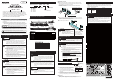
INSTRUCTION MANUAL
Model : CLA
LED Light Bar
Thank you for purchasing the PATLEDs LED Work Light for your
application. Prior to installation, please read through this manual for
proper installation and precautionary steps. In addition, please store
this manual for future reference when performing maintenance, repairs
or inspections. If you have any questions regarding this product,
please contact our PATLITE Sales Representative.
In order to prevent any damage to the user and other personnel or to assets, note
the following:
◆
The following symbols classifies the following precautions into two catagories and
explains the level of harm inflicted when caution is disregarded while using this product.
Displays the warning "Failure to follow warning may lead to death or severe
injury".
Displays the warning "Failure to follow caution may lead from light to medium
injury or maylead to property loss or injury to others".
WARNING
CAUTION
◆
The following symbols indicate and explains the nature of the information to be observed.
This symbol indicates "Enforced", which should be observed and carried out by all means.
This symbol indicates "Prohibited", which should not be carried out by all means.
● In order to avoid danger to the eyes, do not stare into the beam,
do not view directly into the optical instrument, and don't turn the
beam towards someone's eyes. The LED beam is hazardous to
the eyes.
● Do not loosen any screws. It will have an adverse effect on the
protection rating.
● Verify that the specified operating voltage is not exceeded.
● Connect an external fuse for protection from the power supply.
The product can be protected by short-circuiting due to mis-wiring
and overcurrents or overvoltages which can damage it.
● Avoid installation in the following locations:
●
In direct sunlight, near space heaters or places where high
temperatures are present.
● In locations where iron powder, oil, chemical or explosive
gasses, etc., are present.
[Prohibited]
[Enforced]
CAUTION
● Do not modify or disassemble the product. Failure to comply may
result in electric shock or fire.
● After installing this product, be careful not to use this product to
climb onto a machine, or to get anything snagged onto this
product while it is mounted on equipment, etc. Failure to comply
may result in falling off the machinery or product damage may
occur.
● Be sure to disconnect the power when wiring, mounting,
exchanging, or repairing the product. Failure to comply may result
in damage of the internal circuitry and the danger of electric shock
due to short-circuiting.
● Request the installation and wiring to be accompanied by a
professional contractor. Failure to comply may result in electric
shock, fire, or falling from high places.
● When this product is used for security purposes, it should be
inspected daily, and to be used in conjunction with other security
products, in case a malfunction should occur.
● Verify the installation location is a firm location which can handle
the weight of the product and has no adverse vibrations. If
installed in a place where vibration is frequent and/or exceeds the
specifications, damage to the product may occur.
[ Prohibited ]
[ Enforced ]
WARNING
1. For safe application, observe the following:
Safety Precautions
5. Wiring and Proper Use
6. Maintenance and Inspection
7. Specifications
● Be sure to disconnect the power when wiring, mounting, exchanging, or repairing
the product. Failure to comply may result in damage of the internal circuitry and
the danger of electric shock due to short-circuiting.
● Check that the proper voltage is connected before applying power.
● Do not pull on the cable, or try to push it inside the unit. Possible cause of
failure may occur. In addition, allow a margin of slack for the wire and cable to
prevent stress.
● Use a constant-voltage regulated power supply. Possible cause of failure may
occur with the use of a constant current power supply.
● Connect an external fuse for protection from the power supply. The product can
be protected by short-circuiting due to mis-wiring and overcurrents or
overvoltages which can damage it.
● The Protection Rating does not include the cable ends.
If the ends of the cable are in contact with water or exposed
to dew or condensation, refer to the indications below to
dress the cable ends for water resistance.
●
Connect the wire ends in a location which will not expose the ends to water.
● Use Fillers, such as silicon, etc., to seal the cable ends.
Refer to the circled part of the figure below for the sections requiring protection
from water intrusion.
WARNING
CAUTION
[Enforced]
[Enforced]
CAUTION
L95100056
L0099
B