
Data Sheet

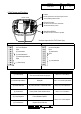


- Non Voltage Contact
AC Power Supply
EHS-
□
H
□
EHS-
□
T
□
Cable
DC Power Supply
- Voltage Contact (EHS-M1 Only)
EHS-
□
H
□
EHS-
□
T
□
Cable
DC Power Supply
* Each channel color is indicated by the cable or lead wire.
* Voltage contact input should be in the range of DC10.8 V to DC31.6 V.
* When using the Terminal type model, round terminals with M3 insulated coating is recommended
when wiring to the Terminal.
Recommended Parts: J.S.T. Manufacturing Co., Ltd. N1.25-3 (article corresponding to RoHS)
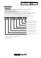
C
D
M2
M1 DC 12 V-DC 24V H Cable
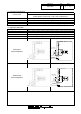
3. Wiring Diagram
AC 100 V-AC 240V T Terminal Buss
M1 H A
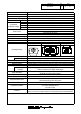
Rated Voltage
2. Model
E H S -
Wiring Specifications
Channel 8 Blue
Channel 7 Green
Channel 6 Orange
Channel 5 Red
Drawing No.
Melody Type
A Type A
E Type E
Type C
Type D
Rev.
Page
F
Terminal Buss
COM Brown
Fuse
Power Supply White
Rated Voltage
Rated Voltage
Channel 1 Lt. Blue
Terminal Buss
COM Brown
Fuse
Channel 6 Orange
Channel 5 Red
Channel 4 Bright green
Channel 3 Pink
Channel 2 Yellow
Power Supply White
DC10.8V-31.6V
Power Supply Black
GND
With NPN Transistor
With PNP Transistor
Insulate
Channel 1 Lt. Blue
Power Supply Black
GND
Channel 8 Blue
Channel 7 Green
Channel 4 Bright green
Channel 3 Pink
Channel 2 Yellow
L
N
+
-
+
-
4/13
EHS-W18