
Manual


-10-
-7-
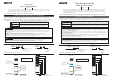
Mounting dimension
4. Installation
■ Mounting
● Drill mounting holes in the wall. (See the mounting dimension.)
● Secure the mounting bracket with the hex bolts and hex nuts.
● Install the Signal Tower vertically at a location that has sufficient strength and minimal
vibration.
● The alarm of buzzer models can be heard best from the front direction.
Therefore make sure the Signal Tower is facing the correct direction before install it.
● This product can be used only indoors. (Do not use it outdoors.)
● Do not install the Signal Tower horizontally or inverted.
(See the following "Mounting side" .)
● Make sure of the specified operating voltage and current before use.
● Do not use or keep without LED unit or Head cover installed.
● Use the soft cloth with moisture when the LED unit or Bse unit must be
cleaned up. (Do not use thinner, benzine, gasoline or oil.)
● During installation, do not remove the waterproof sheet. It may cause
a malfunction of water proof structure.
● This product has 1mm thick waterproof packing at the bottom of the pole
bracket. However, when complete waterproofing is not provided due to the
unevenness of the installation surface, apply waterproof sealant between the
unit and the installation surface to maintain waterproof conditions.
Caution
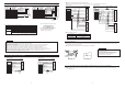
5. Wiring Procedure
■ Wiring procedure (Concerning the mark ※, the conditions about the product corresponding to UL are mentioned.)
● Please make wiring connection according to wiring example.
● For wiring of 5 layers or less, please make wiring connection by increasing or decreasing external contacts in each layer according
to wiring example.
● When using multiple LED units of the same color, make the contact capacity equal to the number of same color LED units multiplied
by the contact capacity for 1 light. (This is because LED units of the same color light up for one signal line.)
※ Fuse for protection of external contact should be installed within 305mm from the connected point of the power source wire.
● When wiring is completed, insulate the end of each unused lead wire by using insulation tape.
※ Use "Class 2 Circuit" for the power supply source. Concerning fuse and fuse-holder, be sure to use the products authorized
by UL Inc.
※ Use the fuse conforming to the rated current of the machine. ( Example : Class J type fuse )
● If you have any questions about simultaneous use of multiple units or other special operations,
contact PATLITE Customer Service before wiring.
Unit:mm
Wiring through hole
(φ13)
Mounting hole
3-φ4
Name plate
Buzzer
transmission
direction
5-1. Wiring for Base unit [Terminal block]
For signal and low voltage
1
2
3
4
5
6
7
8
9
10
Terminal
No.
Red
Orange
Green
Blue
White
Gray
Black
Yellow
Gray
Black
Front
Terminal
color
LED unit Red
LED unit Amber
LED unit Green
LED unit Blue
LED unit White
Buzzer1:Pi…(Continuous)
Buzzer2:Pi・Pi…
Power supply(Continuous COM)
Flashing COM
Power supply
Corresponding unit
or operation
※Recommendable wire type / dia
UL1007AWG22~16
UL1430AWG22~16
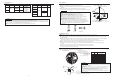
8. Specifications
● In the event that the tower is subject to continuous,excessiv shaking,vibration may be too strong and there is a danger
of breakage. Immediately stop using the tower and consult PATLITE Customer Service.
● PATLITE Corporation disclaims all liability for any malfunction or damage occurring as a result of handling contrary to
the instructions, cautions and warnings mentioned in this manual.
● Specifications may change without notice due to continual product improvement.
Caution
LU5-02
LU5-02FB
24V DC
Mass
Model
Rated voltage
Power consumption
[Base unit]
LU5-E-R
LU5-E-Y
LU5-E-G
LU5-E-B
LU5-E-C
24V DC
Mass
Model
Rated voltage
Power
consumption
[LED unit]
Flashing cycle and
Peak sound level
FB Type
60 Flashes
per minute
Sound level
85dB/m
※FB type only
1.2W
1.1W
0.5W
0.4W
44g
※Use 75℃ CU Wire only.
①
Upright
②
Invert
③
Horizontal
※ Strip length of lead wires: 9mm
VOL.
VOL.
VOL.
● Remove Body from Base unit.( Refer to "6. Unit reformation" .)
[Mounting side]
〔Terminal block〕
●Never fail to observe the strip length of lead wire. Excessively short strip length causes
connection failure and excessively long strip length gives rise to electric shock or short circuit,
which are extremely dangerous.
●While wiring this product, take care to avoid short-circuits from loose wire strands or similar
conditions.
●Do not use unnecessarily strong force to separate the Terminal block and the Body.
Inside wiring may be damaged and may cause failure.
●Connect high-voltage power supply cable to the specified terminals in the Terminal block.
Failure to connect this cable correctly will burn out the internal circuit.
●When removing the lead wire, be sure to operate the lever first, before pulling the wire out.
Caution
① Press the lever with screw driver etc.
② Insert the stripped portion of the lead wire all the way into Terminal block.
③ Release the lever and wiring is completed.
CN2
182g
200g
-Screw driver
Terminal
Lever
Lead wires
φ30
12.5
30°