
Manual


-9-
-8-
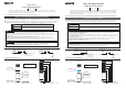
Red・Amber: 52mA Green・Blue・White:42mA
24V DC
360mA
Is≧100mA, Vs≧35V AC
Is≧500mA
Vs≧35V AC
Is≧100mA, Vs≧35V AC
100mA
50mA
Voltage specs.
LED unit
〔1-Light〕
Current consumption
【Recommended external contact capacity】
Power supply
Contact capacity
※Is:Current capacity, Vs:Withstand voltage
Buzzer
Inrush current
Current consumption
● Make sure the power is OFF before wiring. A short circuit may damage internal circuits or cause an electric shock.
● Do not pull out the lead wire or push it into the pole or the body.
● Install the external contact fuse on the power supply side as shown in the wiring example in order to prevent
burn in case of a wiring error.
● Failure to follow wiring instructions may cause damege to product or product may not operate properly.
● Do not apply voltage directly to Flashing common wire. It may cause a breakdown. ( FB type )
● Do not connect Continuous common wire and Flashing common wire. It may damage the internal circuit.
● If using both flashing and continuous circuits, do not apply power at the same time as this may cause second color
indicator to light. This also applies to both alarm circuits.
● If you use the product with both alarms, please use external contacts for lighting and for alarms.
Caution
Contact capacity
Current consumption
Contact capacity
(1A)
5-2. Wiring example
LU5 [ Continuous light type ]
Power
supply
LED White
LED Blue
LED Green
LED Amber
LED Red
External
contact fuse
Continuous COM
Continuous light
External
contact
(1A)
【Recommended external contact fuse】
250V 1A
Ampere rating of fuse
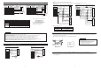
LU5-FB [ Continuous light or Flashing, with Buzzer type ]
Flashing COM
Flashing
LED White
LED Blue
LED Green
LED Amber
LED Red
Buzzer 2
Buzzer 1
Continuous COM
Power supply
External
contact fuse
Continuous light
with Buzzer
External
contact
※Use the fuse conforming to the rated current of
the machine which you install product.
(Example : UL Class J type fuse)
Power supply
■LU5- FB [ Continuous light or Flashing, with Buzzer type ]
PNP Transistor
NPN Transistor
LED White
LED Blue
LED Green
LED Amber
LED Red
(1A)
Power supply wire
Current capacity
Vc≧35V
IL≦0.1mA
(LED unit)
(Buzzer)
Dielectric break
down strength
Leak current
Continuous
I/O Unit
Power
Supply
External
contact
Fuse
Buzzer 1
Buzzer 2
Continuous COM
Flashing COM
External
contact fuse
Continuous
I/O Unit
Flashing
I/O Unit
Flashing COM
Continuous COM
24V DC
24V DC
● When you use FB (Continuous light or Flashing, with Buzzer) type, you need the I/O unit respectively.
■Recommendation transistor
LED White
LED Blue
LED Green
LED Amber
LED Red
Buzzer 1
Buzzer 2
Power supply
Flashing
I/O Unit
Power
Supply
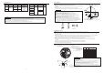
1
2
3
4
5
6
7
8
9
10
Terminal
No.
Red
Orange
Green
Blue
White
Gray
Black
Yellow
Gray
Black
Terminal
color
LED unit Red
LED unit Amber
LED unit Green
LED unit Blue
LED unit White
Buzzer1:Continuous
Buzzer2:Pi・Pi・・
Power supply(Continuous COM)
Flashing COM
Power supply
Corresponding unit
or operation
[CN2]
[CN2]
1
2
3
4
5
6
7
8
9
10
Terminal
No.
Red
Orange
Green
Blue
White
Gray
Black
Yellow
Gray
Black
Terminal
color
1
2
3
4
5
6
7
8
9
10
Terminal
No.
Red
Orange
Green
Blue
White
Gray
Black
Yellow
Gray
Black
Terminal
color
(1A)
(Non polar)
Power
supply
(Non polar)
5-3. NPN ( PNP ) Transistor drive example
Continuous
COM
(1A)
(1A)
24V DC
Continuous
I/O Unit
Power
Supply
External
contact
fuse
LED White
LED Blue
LED Green
LED Amber
LED Red
Power
Supply
External
contact fuse
24V DC
■LU5 [ Continuous light ]
PNP Transistor
NPN Transistor
Continuous
COM
LED White
LED Blue
LED Green
LED Amber
LED Red
[CN2]
[CN2]
1
2
3
4
5
6
7
8
9
10
Terminal
No.
Red
Orange
Green
Blue
White
Gray
Black
Yellow
Gray
Black
Terminal
color
1
2
3
4
5
6
7
8
9
10
Terminal
No.
Red
Orange
Green
Blue
White
Gray
Black
Yellow
Gray
Black
Terminal
color
Continuous
I/O Unit
Ic≧100mA
● Please use a fuse specified by IEC 127.
● When lead wires are exposed outside the body during pole installation, etc. always provide double insulation using insulation tape
and vinyl tubing, etc.
7. To use this product in accordance with the CE marking, please observe the followings
●Turn the power OFF before performing unit reformation.
●First make sure the O-ring is mounted as shown in Drawing 1,then align the locating mark of each unit,and place the units together in
the direction of the arrow (①) as shown.
●Rotate the upper unit in the direction of the arrow(②).(Refer to Drawing.2)
6. Unit reformation
Caution
● Do not remove a LED unit forcibly.
It may damage the unit.
● Do not warp or damage the LED unit to a lower unit.
● Make sure the O-ring is first mounted in position on
the Terminal block as shown in Drawing 1,
then place the Body on the O-ring.
Drawing.1
Drawing.2
1
22
a
O ring